Electronic controller

a technology of electronic controllers and sealing materials, applied in the direction of electrical apparatus casings/cabinets/drawers, basic electric elements, semiconductor devices, etc., can solve the problems of difficult identification of a portion from which air leakage is to be established, inability to easily check, and inability to conduct such tasks in a fabrication line for electronic controllers, etc., to achieve the effect of reducing the rejection ratio in the test, improving assembly operation, and high possibility of air leakag

Active Publication Date: 2013-05-16
MITSUBISHI ELECTRIC CORP
View PDF7 Cites 29 Cited by
  • Summary
  • Abstract
  • Description
  • Claims
  • Application Information

AI Technical Summary

Benefits of technology

[0017]According to the electronic controller of the present invention, the space enabling the application state of the sealing material to be observed with the naked eye from the exterior, in a state in which the casing members are joined together, is provided to the area in which the casing members are to be joined together. Therefore, the portion applied with the small amount of the sealing material, which has the high possibility of air leakage from the area in which the casing members are to be joined together can be visually identified. As a result, by additionally applying the sealing material before the airtightness test is conducted, the reject ratio in the test can be reduced and the efficiency of assembly operation can be improved.
[0018]Further, by applying the sealing material only to the portion applied with the small amount of sealing material when the sealing material is to be additionally applied, the use of the appropriate amount of the sealing material can be attained, and thus the unnecessary use of the sealing material can be eliminated.

Problems solved by technology

In the case of the electronic controller described above, however, the application amount of the sealing material on the area of the casing, in which a joint is to be established, cannot be easily checked.
Therefore, it is difficult to identify a portion from which air leaks, specifically, a portion which requires to be additionally applied with the sealing material.
However, conducting such tasks in a fabrication line for the electronic controllers is not practical in view of a line space, capital investment, and fabrication cost.
As described above, the conventional electronic controllers have had a problem in that it is difficult to identify a portion with a small amount of the sealing material, which has a high possibility of air leakage, and to additionally apply the sealing material only to the identified portion at the location of assembly.
In this case, however, there arises another problem in that the amount of the sealing material to be used disadvantageously increases, thereby increasing the cost of the electronic controller.

Method used


Image

  • Electronic controller
  • Electronic controller
  • Electronic controller

Examples


embodiment 1

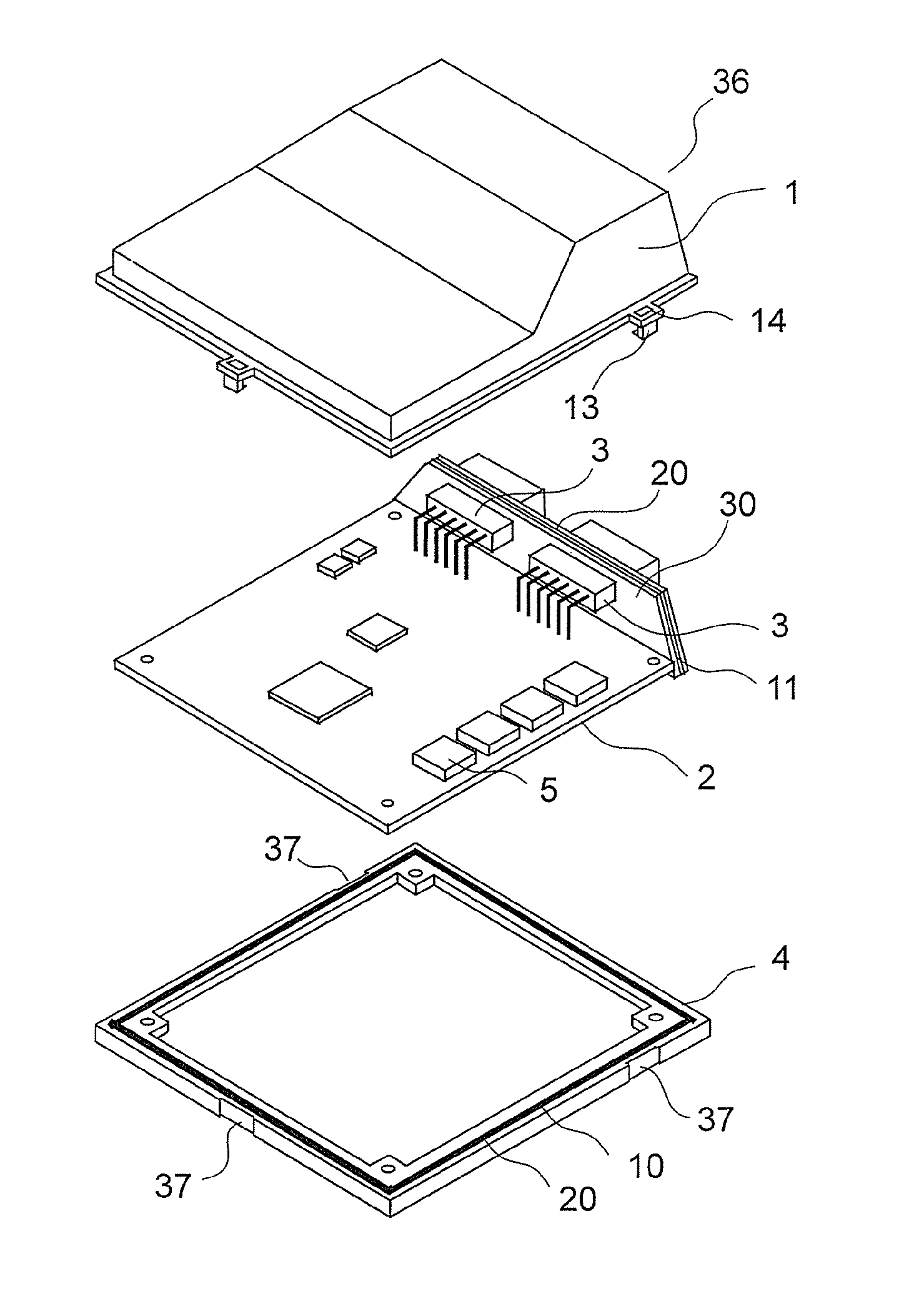
[0031]FIG. 1 is an exploded perspective view schematically illustrating a structure of an electronic controller according to Embodiment 1 of the present invention.

[0032]The electronic controller includes an electronic circuit board 2 having electronic components 5 mounted thereon, and a casing which houses the electronic circuit board 2 therein.

[0033]The casing includes a base 4, a cover 1, and a lid 30. The base 4 and the cover 1 interpose the electronic circuit board 2 from both sides to cover the electronic circuit board 2. The lid 30 supports connectors 3, each being electrically connected to the electronic circuit board 2, and closes an opening portion 36 formed by the base 4 and the cover 1.

[0034]Note that, the lid 30 and the connectors 3 may be formed as one component instead of being formed as separate members.

[0035]In this embodiment, casing members constituting the casing are the base 4, the cover 1, and the lid 30.

[0036]As a material of the cover 1, the base 4, and the li...

embodiment 2

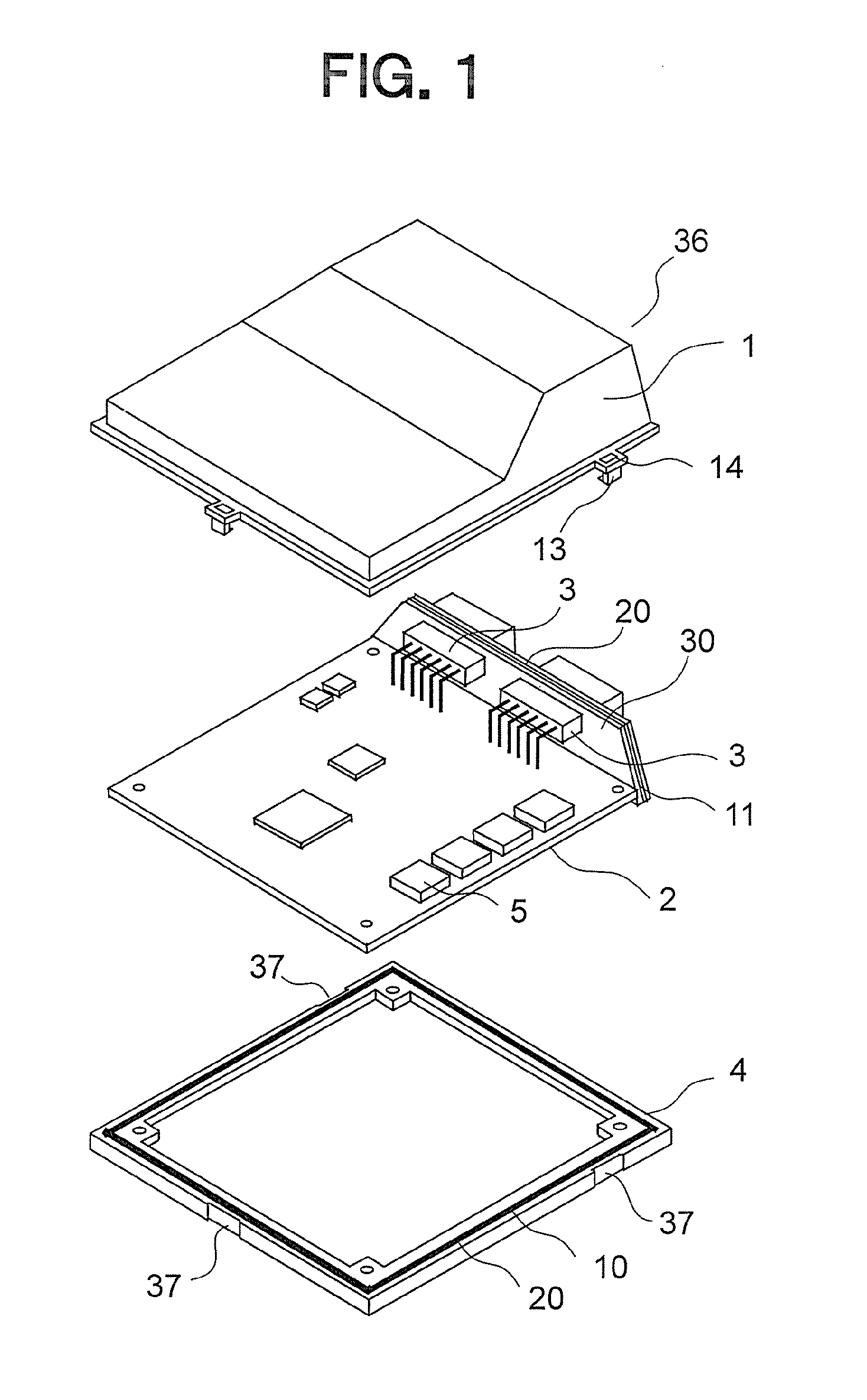
[0064]FIG. 4A is a sectional view of a principal part of the cover 1 and the base 4 of an electronic controller according to Embodiment 2 of the present invention before the cover 1 and the base 4 are joined together, whereas FIG. 4B is a sectional view of the principal part of the cover 1 and the base 4 after the cover 1 and the base 4 are joined together.

[0065]In this embodiment, a jetty 18 is provided to the cover 1 so as to be formed on an inner side of a projection 12A and be opposed to the projection 12A. A dimension of the jetty 18 toward the base 4 is longer than a dimension of the projection 12A toward the base 4.

[0066]The remaining configuration is the same as that of the electronic controller of Embodiment 1.

[0067]In this embodiment, before the projection 12A of the cover 1 presses and flattens the sealing material 20, an inner wall surface 40 of the jetty 18 comes into contact with an inner wall surface 35 of the base 4, and then the jetty 18 is lowered while blocking an...

embodiment 3

[0071]FIG. 5 is an exploded sectional view schematically illustrating a structure of an electronic controller according to Embodiment 3 of the present invention. FIG. 6A is a sectional view of a principal part of a casing main body 7 and a lid 30A illustrated in FIG. 5 before the casing main body 7 and the lid 30A are joined together, whereas FIG. 6B is a sectional view of the principal part of the casing main body 7 and the lid 30A after the casing main body 7 and the lid 30A are joined together.

[0072]The electronic controller according to Embodiment 3 includes the casing main body 7 and the lid 30A. The casing main body 7 is a casing member which houses an electronic circuit board2A therein. The lid 30A is a casing member which supports connectors 3A electrically connected to the electronic circuit board 2A and closes an opening portion 36A of the casing main body 7.

[0073]Note that, the lid 30 and the connectors 3A may be formed as one component instead of being formed as separate...


PUM


Abstract

Provided is an electronic controller which enables visual identification of a portion applied with a small amount of a sealing material, which has a high possibility of air leakage from an area in which a joint is to be established. The electronic controller includes: an electronic circuit board; and a casing including a cover (1), a base (4), and a lid sealed with a sealing material (20) applied to surfaces thereof at which the cover (1), the base (4), and the lid are to be joined together. An area in which the cover (1), the base (4), and the lid are to be joined together is provided with a space (16) thereto for enabling an application state of the sealing material (20) to be observed with a naked eye.

Description

BACKGROUND OF THE INVENTION[0001]1. Field of the Invention[0002]The present invention relates to an electronic controller which includes electronic components mounted on an electronic circuit board housed within a casing.[0003]2. Description of the Related Art[0004]An electronic controller, which is used for controlling a vehicle or the like, includes an electronic circuit board, a plurality of electronic components, and a casing. On the electronic circuit board, connectors for electrical connection to the exterior are provided. The plurality of electronic components are mounted on the electronic circuit board. The casing is made of a resin or a metal. The electronic circuit board is housed in the casing for protection of the electronic components.[0005]Among various types of electronic controller, an electronic controller provided in an engine room or directly mounted on an engine has a water-proof structure in view of a possibility of getting wet with water. As an example of the e...

Claims


Application Information

Patent Timeline
Patent Type & Authority Applications(United States)
IPC IPC(8): H05K5/06H05K7/14
CPCH05K5/0052H05K5/069H05K5/062H05K5/0039H01L2924/163
Inventor TAMURA, MASAKOTAKAHASHI, YASUHIROKUBO, TORUKATO, SEIJITANAKA, TAKAAKIUMEMOTO, HIDEKI
Owner MITSUBISHI ELECTRIC CORP
Why Eureka
Try Eureka