Container Auto-Lock System

Active Publication Date: 2013-05-16
BNSF RAILWAY
View PDF3 Cites 33 Cited by
  • Summary
  • Abstract
  • Description
  • Claims
  • Application Information

AI Technical Summary

Problems solved by technology

The manual locking/unlocking and stowing of eac

Method used


Image

  • Container Auto-Lock System
  • Container Auto-Lock System
  • Container Auto-Lock System

Examples


Embodiment Construction

[0022]Illustrative embodiments of the system of the present application are described below. In the interest of clarity, not all features of an actual implementation are described in this specification. It will of course be appreciated that in the development of any such actual embodiment, numerous implementation-specific decisions must be made to achieve the developer's specific goals, such as compliance with system-related and business-related constraints, which will vary from one implementation to another. Moreover, it will be appreciated that such a development effort might be complex and time-consuming, but would nevertheless be a routine undertaking for those of ordinary skill in the art having the benefit of this disclosure.

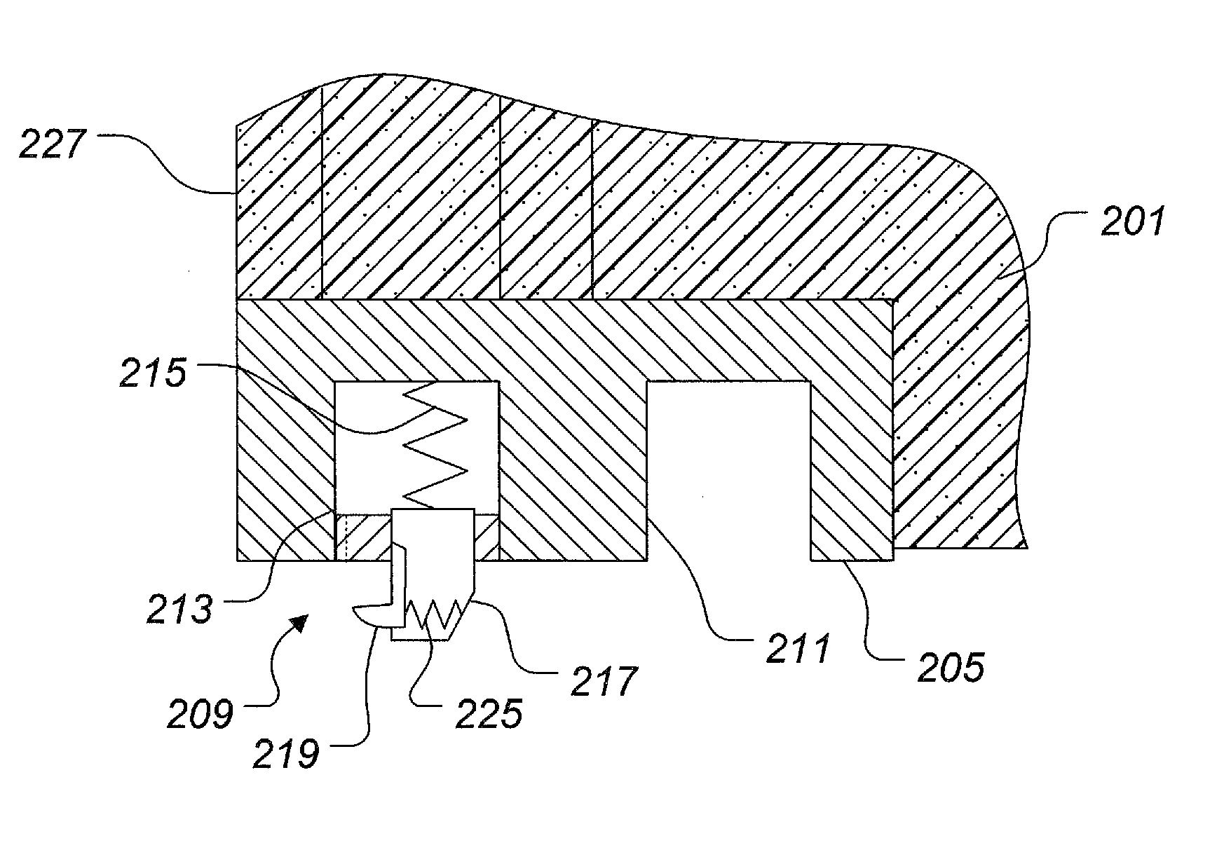
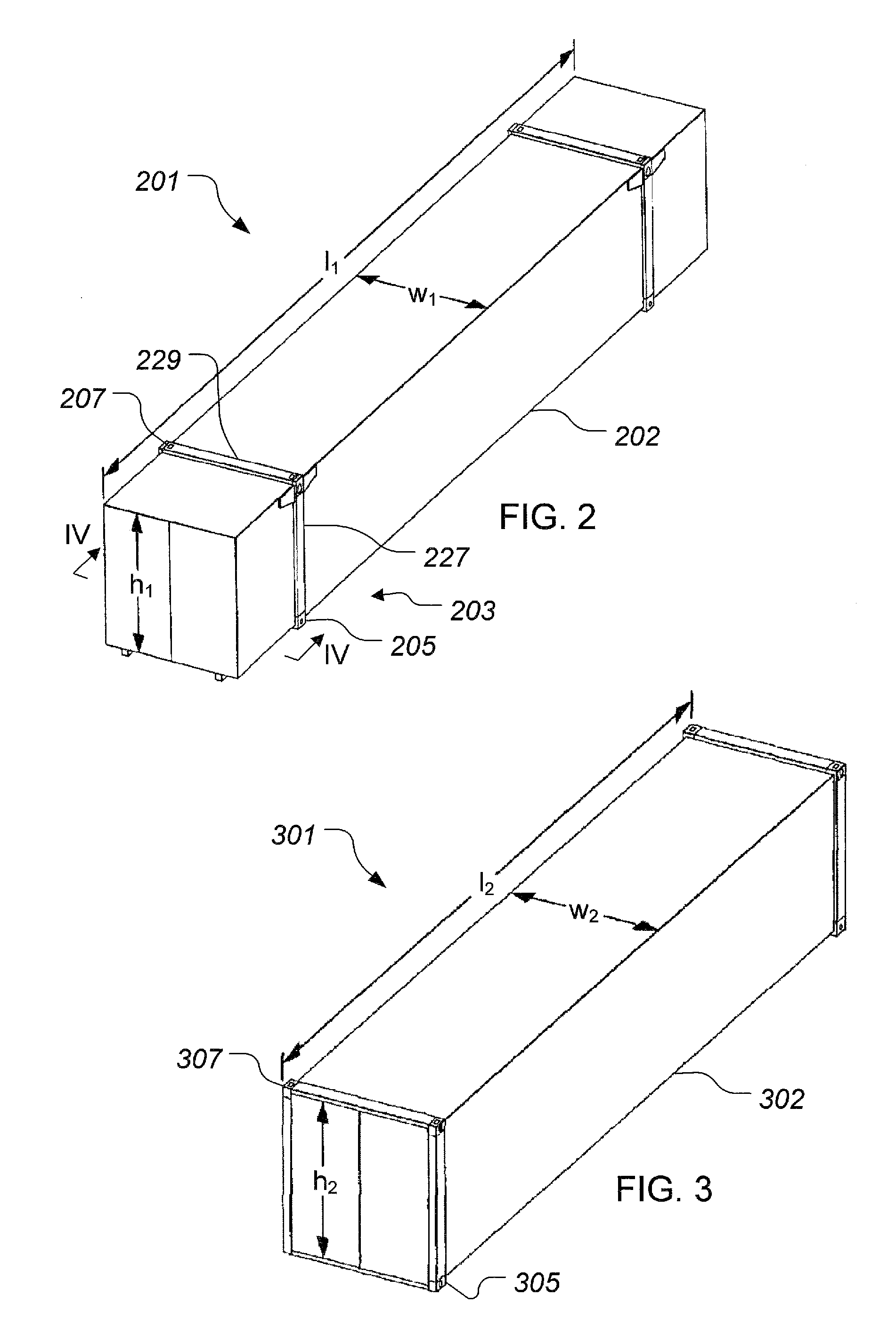
[0023]Referring to FIG. 2, a container 201 having a container auto-lock system (“CALS”) 203 according to the present application is illustrated. Container 201 is a WTP (wide-to-pick) domestic sized container typically having a length l1 of 53′ and a width ...


PUM

PropertyMeasurementUnit
Sizeaaaaaaaaaa
Heightaaaaaaaaaa
Frictionaaaaaaaaaa

Abstract

A container according the present application includes a container auto-lock system. The container auto-lock system is integrated into the outboard apertures of the lower castings of a domestic sized container. The container auto-lock system includes a locking mechanism which is configured to recess when the container is lowered onto a surface lacking an acceptable receiving aperture. The locking mechanism is also configured to automatically lock when placed on top of a domestic sized container. The container auto-lock system is configured to be compatible with international sized container by allowing the inboard apertures on each lower casting to be available for attaching the domestic container on top of an international container with a conventional locking device.

Description

BACKGROUND[0001]1. Field of the Invention[0002]The system of the present application relates to a freight container auto-lock system and method for operating the system.[0003]2. Description of Related Art[0004]Freight containers are commonly used for transporting cargo by ship and rail. Typically freight containers are rectangular and exist in various sizes. A typical freight container has corner castings, or castings near the corners. The castings have one or more apertures which are configured for coupling together adjacent containers. Many freight operators use inter-box connecters (“IBC's”) to attach stacked freight connectors together. IBC's are non-integral with the containers themselves. Furthermore, the IBC's are manually operated to connect the stacked containers via the corner castings. It is desirable for a freight operator to unload freight containers from a rail as expeditious as possible.[0005]Referring to FIG. 1, an IBC 101 is illustrated in conjunction with a lower c...

Claims


Application Information

Patent Timeline
IPC IPC(8): B60P7/13
CPCB65D90/0013B60P7/13B65D88/027B65D90/48Y10T29/49826
Inventor KELLY, THOMAS P.
Owner BNSF RAILWAY
Why Eureka
Try Eureka