Apparatus and Method for Die Bonding

Inactive Publication Date: 2013-05-16
WALSIN LIHWA
View PDF4 Cites 15 Cited by
  • Summary
  • Abstract
  • Description
  • Claims
  • Application Information

AI Technical Summary

Benefits of technology

[0018]Thereby, the die bonding apparatus and the die bonding method of the present invention can provide a fast die bonding speed due to the simultaneous bonding of a plurality of dies and a desirable bonding accuracy due to the use of a die sucking device. In addition, the drawbacks of the co

Problems solved by technology

The LED dies are sucked and bonded one by one in the sequential die bonding method; therefore, it takes a very long time to bond all the dies.
However, the time-consuming sequential die bonding method is still adopted the pre-bonding stage of the die bonding process, and this two-stage bonding process is not suitable for all LED die bonding processes.
In addition, the accuracy of the die bonding process is significantly degraded by elimi

Method used


Image

  • Apparatus and Method for Die Bonding
  • Apparatus and Method for Die Bonding
  • Apparatus and Method for Die Bonding

Examples


Embodiment Construction

[0026]Hereinbelow, the die bonding apparatus and the die bonding method of the present invention will be described with reference to embodiments thereof. However, it shall be appreciated that the attached drawings are depicted in a slightly simplified or slightly exaggerative way to facilitate the understanding of the present invention. The numbers, shapes and dimensional scales of elements shown in the attached drawings are unnecessarily the same as those in actual implementations and are not intended to limit the present invention.

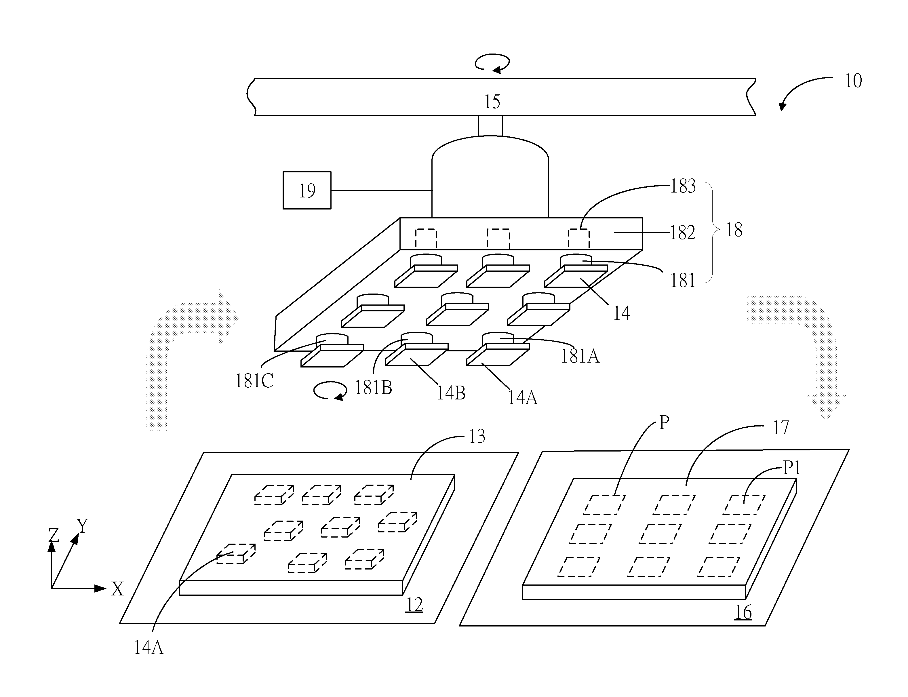
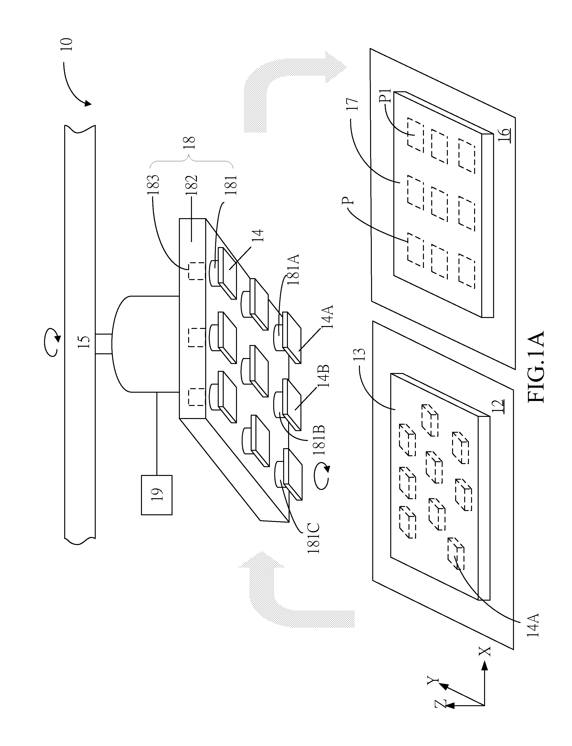
[0027]First, FIG. 1A illustrates a schematic view of a die bonding apparatus 10 according to a first preferred embodiment of the present invention. The feature of the bonding apparatus 10 of this embodiment is that it can suck a plurality of dies simultaneously, sequentially, or partially simultaneously and partially sequentially, and finely adjust the relative positions among the dies to accurately position the dies before simultaneously bonding the die...


PUM

PropertyMeasurementUnit
Areaaaaaaaaaaa
Vacuumaaaaaaaaaa

Abstract

A die bonding apparatus and a die bonding method are provided, which are capable of simultaneously bonding a plurality of dies from a first placement area onto a substrate disposed on a second placement area. The die bonding apparatus includes a die sucking device which is movably located above the first placement area and a second placement area. The die sucking device includes a plurality of nozzles. The nozzles can suck the dies disposed on the first placement area, and then simultaneously bond the dies onto the substrate.

Description

[0001]This application claims priority to Taiwan Patent Application No. 100141509 filed on Nov. 15, 2011, the disclosure of which is incorporated herein by reference in its entirety.CROSS-REFERENCES TO RELATED APPLICATIONS[0002]Not applicable.BACKGROUND OF THE INVENTION[0003]1. Field of the Invention[0004]The present invention provides a die bonding apparatus and a die bonding method, and more particularly, to a die bonding apparatus and a die bonding method capable of simultaneously bonding a plurality of dies.[0005]Descriptions of the Related Art[0006]In recent years, light emitting diodes (LEDs) have become the major development focus of green light sources in the future because of their advantages, such as energy-saving and long service life. Currently, the packaging process of LEDs usually uses a single sucking device having to suck an LED die from an adhesive film and then place the LED die onto a substrate (or a base) one by one so as to complete the die bonding process of th...

Claims


Application Information

Patent Timeline
IPC IPC(8): H01L21/66B32B41/00B32B38/18
CPCH01L21/6838H01L24/75H01L33/0095H01L24/97H01L2224/75745H01L2224/75753Y10T156/1702H01L2224/7598H01L2224/75842H01L2924/12041H01L2224/97H01L2924/00H01L2924/15787H01L2924/15788
Inventor CHUNG, JUN-WEILOU, WEI-CHENGWU, JUNG-KUNCHIANG, CHUNG-I
Owner WALSIN LIHWA
Why Eureka
Try Eureka