
Terminal pair

Active Publication Date: 2013-05-16
YAZAKI CORP
View PDF3 Cites 8 Cited by
  • Summary
  • Abstract
  • Description
  • Claims
  • Application Information

AI Technical Summary

Benefits of technology

This invention is about a way to attach terminals to a member using a lock and lock-receiving portion. The locking portion and the lock-receiving portion are separate, which makes it easier to fix the terminals to the member. The terminals are securely fixed to each other, and their relative position remains stable. This invention ensures that the terminals can be easily attached to the member and maintain their proper positioning.

Problems solved by technology

Namely, it is difficult to maintain a position relationship of the terminals relative to each other in a regular position relationship.
Further, because a pair of terminals is separated from each other, it is difficult to position the terminals relative to each other, and to position terminals relative to a vehicle body until the bolt inserted into a through hole is screwed into the weld nut.

Method used


Image

  • Terminal pair
  • Terminal pair
  • Terminal pair

Examples


Embodiment Construction

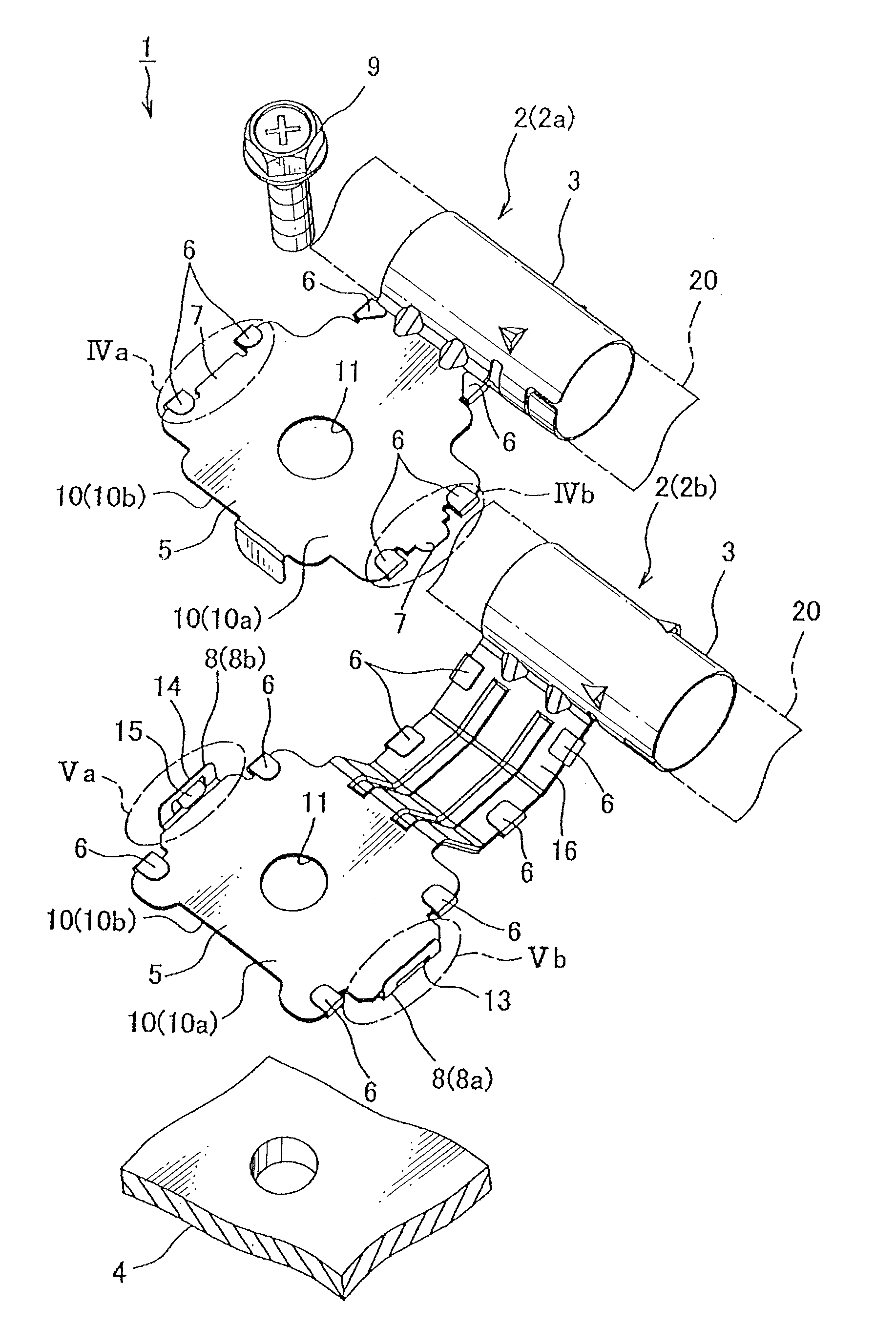
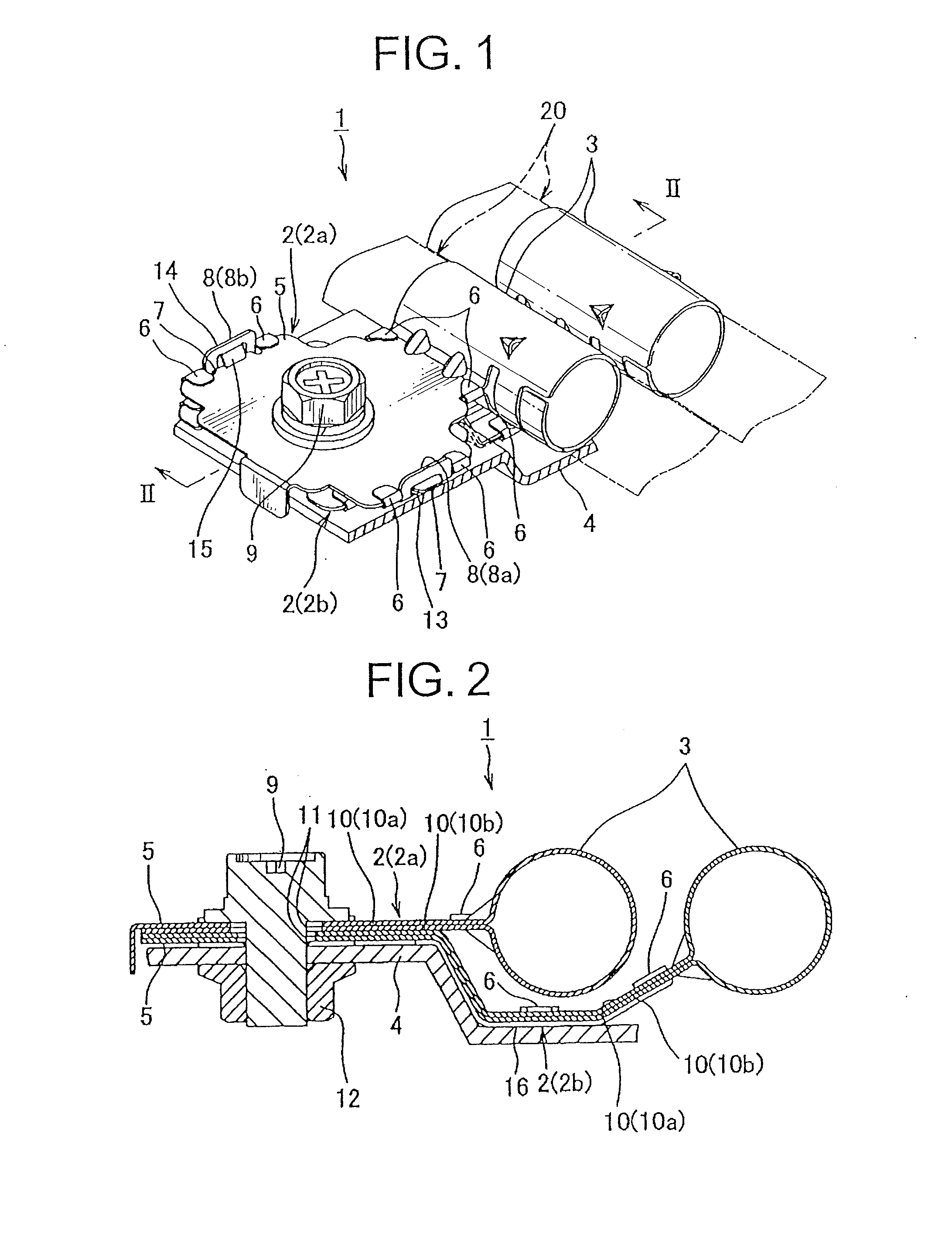
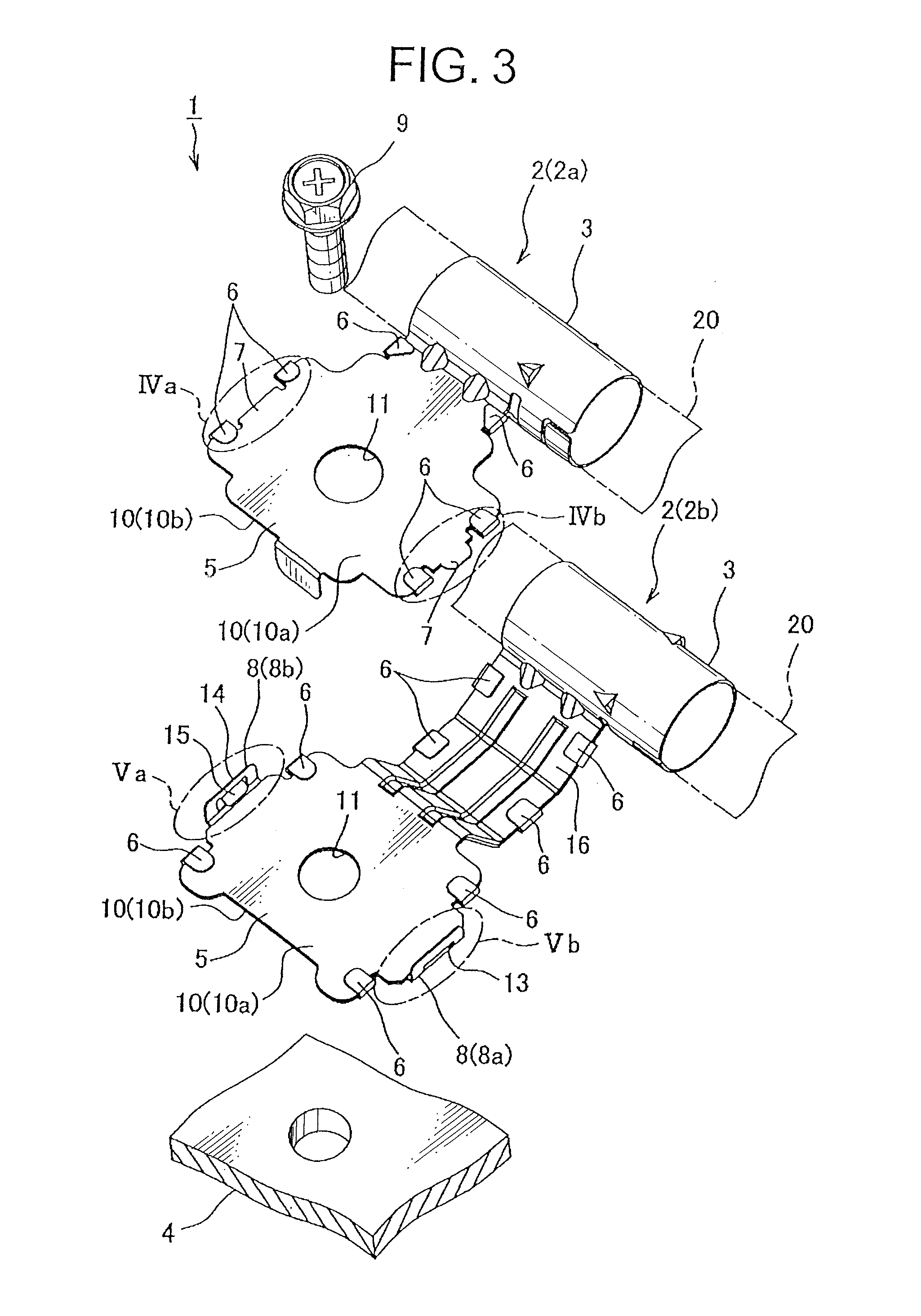
[0042]Hereinafter, a terminal pair according to an embodiment of the present invention will be explained with reference to FIGS. 1 to 7. A terminal pair 1 shown in FIG. 1 includes: a pair of terminals 2a, 2b; a plurality of locking portions 7; and a plurality of lock-receiving portions 8 as shown in FIGS. 1 to 3. The terminals 2a, 2b are respectively made by punching and folding a metal plate 10. As shown in FIG. 3, each of the terminals 2a, 2b integrally includes: a cylindrical shield fixing portion 3; an attaching portion 5 configured to be attached to a vehicle body panel 4 (corresponding to the attached member) composing a vehicle body as an earth; a plurality of crimping pieces 6. The shield fixing portion 3 is disposed at the center of the metal plate 10.

[0043]The shield fixing portion 3 is attached to a shielded wire 20 in a condition to be electrically connected to the braid of the shielded wire 20 when an outer cover of the shielded wire 20 is removed, and a place where the...


PUM


Abstract

A terminal pair 1 includes: a pair of terminals 2a, 2b; a plurality of locking portions 7; and a plurality of lock-receiving portions 8a, 8b. Each of the terminals includes: a shield fixing portion 3 to which the shielded wire 20 is attached; and an attaching portion 5 continued to the shield fixing portion 3 and attached to a vehicle body panel 4 by overlapping with the vehicle body panel 4 and fastening to the vehicle body panel 4 with a bolt 9. The locking projections 7 are provided on the attaching portion 5 of one terminal 2a of the pair of terminals 2a, 2b. The lock-receiving projections 8a, 8b are provided on the attaching portion 5 of the other terminal 2b, and locked by the locking portions 7.

Description

TECHNICAL FIELD[0001]This invention relates to a terminal pair configured to be attached to a braid of a shielded wire or the like and to connect the braid. with an attached member such as a vehicle body.BACKGROUND ART[0002]A shielded wire is often arranged in a vehicle as a moving object. Various terminal pairs (for example, see Patent document 1) are used for electrically connecting the braid of the shielded wire as an earth with a vehicle body. Such a terminal pair includes a pair of terminals. The terminal is respectively made by punching and folding a metal plate. The terminal integrally includes: a cylindrical shield fixing portion; and an attaching portion attached to a vehicle body as the earth (corresponding to an attached member).[0003]The shield fixing portion is attached to a shielded wire in a condition to be electrically connected to the braid of the shielded wire when an outer cover of the shielded wire is removed, and a place where the braid is exposed is inserted in...

Claims


Application Information

Patent Timeline
IPC IPC(8): H01R4/48
CPCH01R4/646H01R4/34H01R4/48H02G3/32H01R11/09H01R11/12
Inventor DENO, MASAHIROTSUSHIMA, YOSHITAKA
Owner YAZAKI CORP
Learn More