Tank valve unit

Active Publication Date: 2010-03-04
TOYODA GOSEI CO LTD
View PDF17 Cites 10 Cited by
  • Summary
  • Abstract
  • Description
  • Claims
  • Application Information

AI Technical Summary

Benefits of technology

[0009]According to this first mode, the means for securing the fuel cutoff valve to the support body involves integrally forming on the bottom cover a first engaging portion adapted to engage the valve engaged portion of the casing body, and a second engaging portion adapted to engage the support engaged portion of the housing portion of the support body, that is, not only is the bottom cover provided with engaging means adapted to

Problems solved by technology

In one known design for a tank valve unit of this kind, a fuel cutoff valve is installed on a support body by being attached through screw fastening, welding, or the like, for example see JP 1-301227 A. However, such prior

Method used


Image

  • Tank valve unit
  • Tank valve unit
  • Tank valve unit

Examples


Example

[0016](1) General Configuration of Fuel Tank Valve Unit

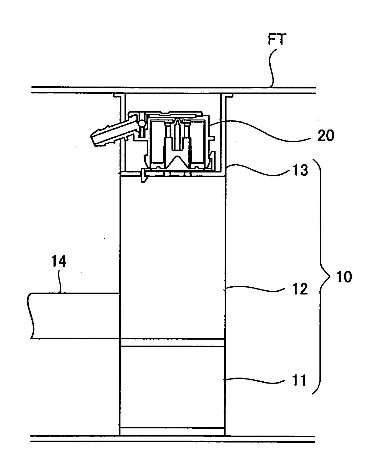
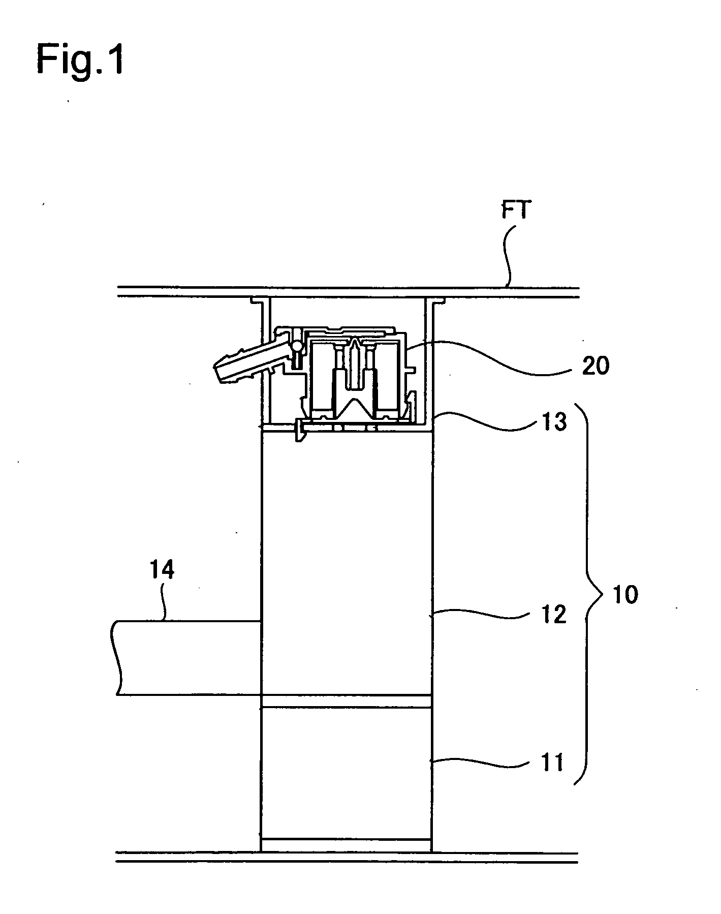
[0017]FIG. 1 is a sectional view depicting an automobile fuel tank FT that employs a tank valve unit in accordance with an embodiment of the present invention. The fuel tank FT is formed by laminating several resin material layers, and is manufactured by a known art method, specifically, by extruding a tubular parison into a mold. A support body 10 and a fuel cutoff valve 20 are situated inside the fuel tank FT. The support body 10 is a member adapted for mounting the fuel cutoff valve 20, as well as to enhance the support structure of the fuel tank and to reduce fuel wave action. The fuel cutoff valve 20 is of so-called in-tank design, and is provided as a valve adapted to restrict outflow of fuel to the outside if the fuel level in the fuel tank FT rises when the vehicle tilts or when the vehicle turns sharply.

[0018](2) Configuration of Support Body 10

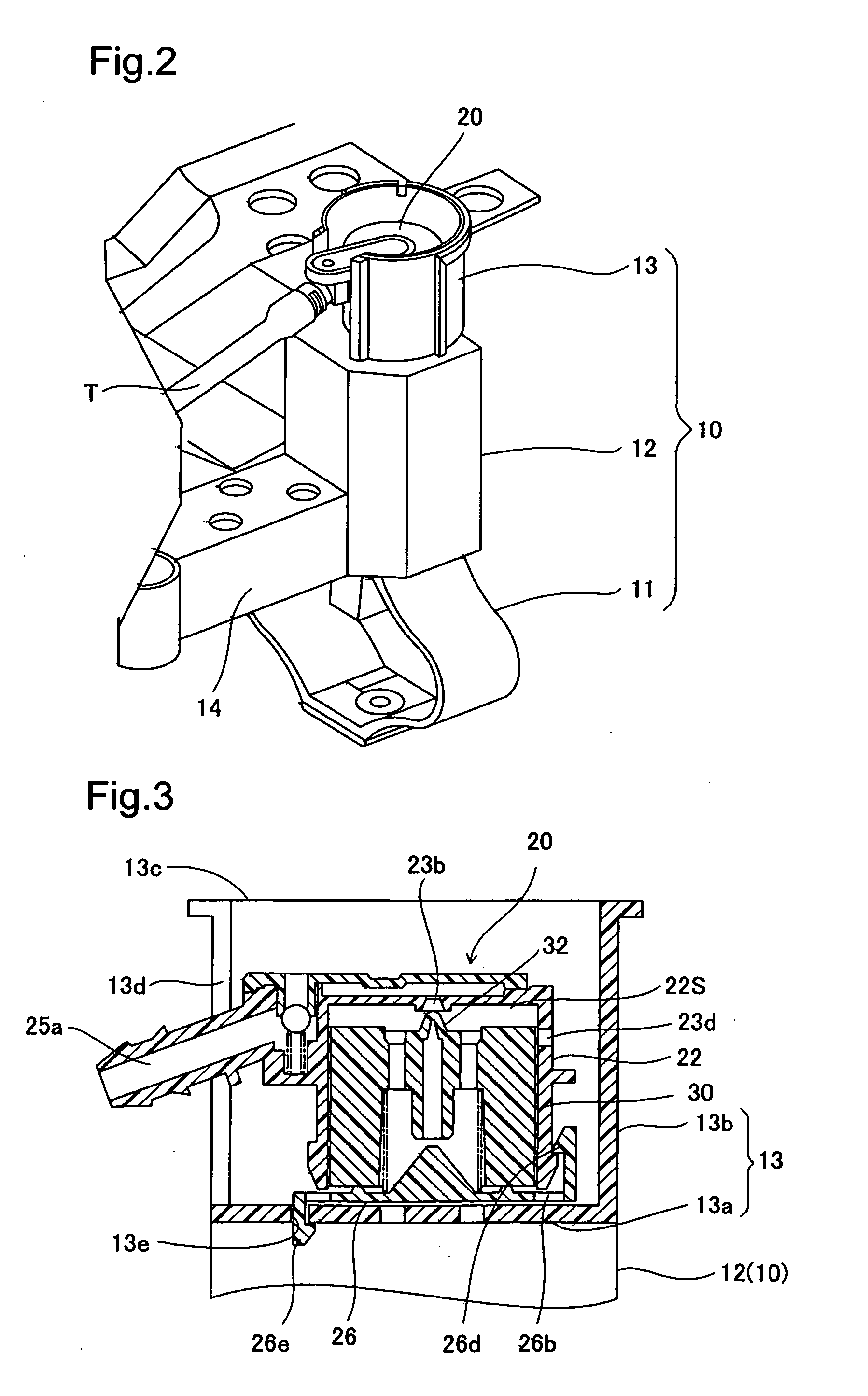
[0019]FIG. 2 is a perspective view showing part of the tank valve unit. The ...


PUM


Abstract

The tank valve unit includes a support body, and a fuel cutoff valve installed on the support body. The support body includes a mounting plate having a support engaged portion. The fuel cutoff valve has a casing in which a valve chamber is defined by a tubular casing body and a bottom cover installed in the bottom part of the casing body; and a float mechanism housed inside the valve chamber. The bottom cover has a first engaging portion adapted to attach to the casing body by engaging the casing body, and a second engaging portion adapted to secure to the mounting plate by engaging the support engaged portion.

Description

[0001]This application claims the benefit of and priority from Japanese Application No. 2008-221023 filed Aug. 29, 2008, the content of which is incorporated herein by reference.BACKGROUND OF THE INVENTION[0002]1. Field of the Invention[0003]The present invention relates to a tank valve unit having a fuel cutoff valve installed on a support body that is housed inside a fuel tank.[0004]2. Description of the Related Art[0005]In one known design for a tank valve unit of this kind, a fuel cutoff valve is installed on a support body by being attached through screw fastening, welding, or the like, for example see JP 1-301227 A. However, such prior art designs for attaching a fuel cutoff valve to a support body have the problems of an increased number of parts due to the need for screws, and of requiring a laborious operation for attaching or welding the components.SUMMARY[0006]An advantage of some aspects of the invention is to provide a tank valve unit whereby through a simple design a f...

Claims


Application Information

Patent Timeline
IPC IPC(8): F16K21/00
CPCF16K24/04F16K17/36Y10T137/3099Y10T137/0874Y10T137/6004
Inventor YAMADA, NORIHIROIMAEDA, TOMOHISANOJIRI, MASANORI
Owner TOYODA GOSEI CO LTD
Why Eureka
Try Eureka