Remotely-operated rope-threading tool

a remote-operated, rope-threading technology, applied in the direction of lifting devices, ropes and cables for vehicles/pulleys, sport apparatus, etc., can solve the problems of devices requiring devices, personal safety risks of people, and objects tied to ropes that present their own disadvantages and hazards, so as to achieve convenient attachment

Active Publication Date: 2011-02-24
JANTZEN
View PDF8 Cites 10 Cited by
  • Summary
  • Abstract
  • Description
  • Claims
  • Application Information

AI Technical Summary

Benefits of technology

The reel assembly is of a universal design so that it can be used on clamp assemblies that are designed to receive one or two reels. The reel itself is a retractable spring-powered reel, which includes a drum to wind on a length of webbing. The webbing is long enough to activate a tool when the pole is fully extended. The reel could be offered for sale in several sizes or lengths. The end of the webbing has a clasp to easily attach it to a loop in the end of the tool's control cord.

Problems solved by technology

To accomplish these tasks using current methods requires personnel to incur varying degrees of personal safety risk.
Falls are a major cause of injuries.
Throwing objects tied to ropes presents its own disadvantages and hazards.
This method requires aiming skill, the weight may come loose and fly unrestrained, the weight may become entangled, the weight may swing back and strike the thrower or others, or the weight may cause damage as it completes its trajectory.
The main detraction is that these devices require the device to be pushed against the object to activate.
The other objection is the device must be large in relation to the eye.
Deichman attempts to solve these but is not successful because the rope itself pushes on the object.
The arm of this device also sweeps a large arc which is a serious disadvantage.
This device has the disadvantage that it has wide arms relative to the target object, the arms sweep through arcs which would prevent its use if there were other obstructing objects nearby.
Also, it is disadvantaged in that it cannot pass a rope through a small hole.
Other devices are found in the prior art; however they have significant disadvantages.
They have a wide path of action so they cannot work in restricted areas.
Other disadvantages are that some require a fixed object to act against, therefore they can't thread through soft eyes like a cloth loop on a life preserver for example.
The prior art attempts to pass a rope around an object but is not successful in passing a rope around nearly any size of object as well as through a range of hole sizes and configurations.

Method used


Image

  • Remotely-operated rope-threading tool
  • Remotely-operated rope-threading tool
  • Remotely-operated rope-threading tool

Examples


Embodiment Construction

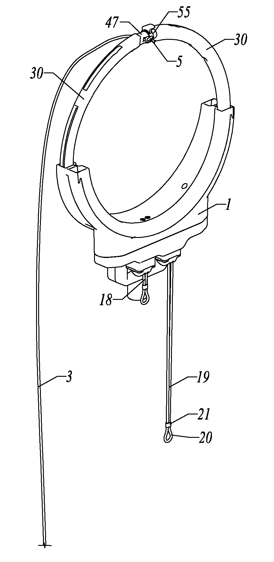
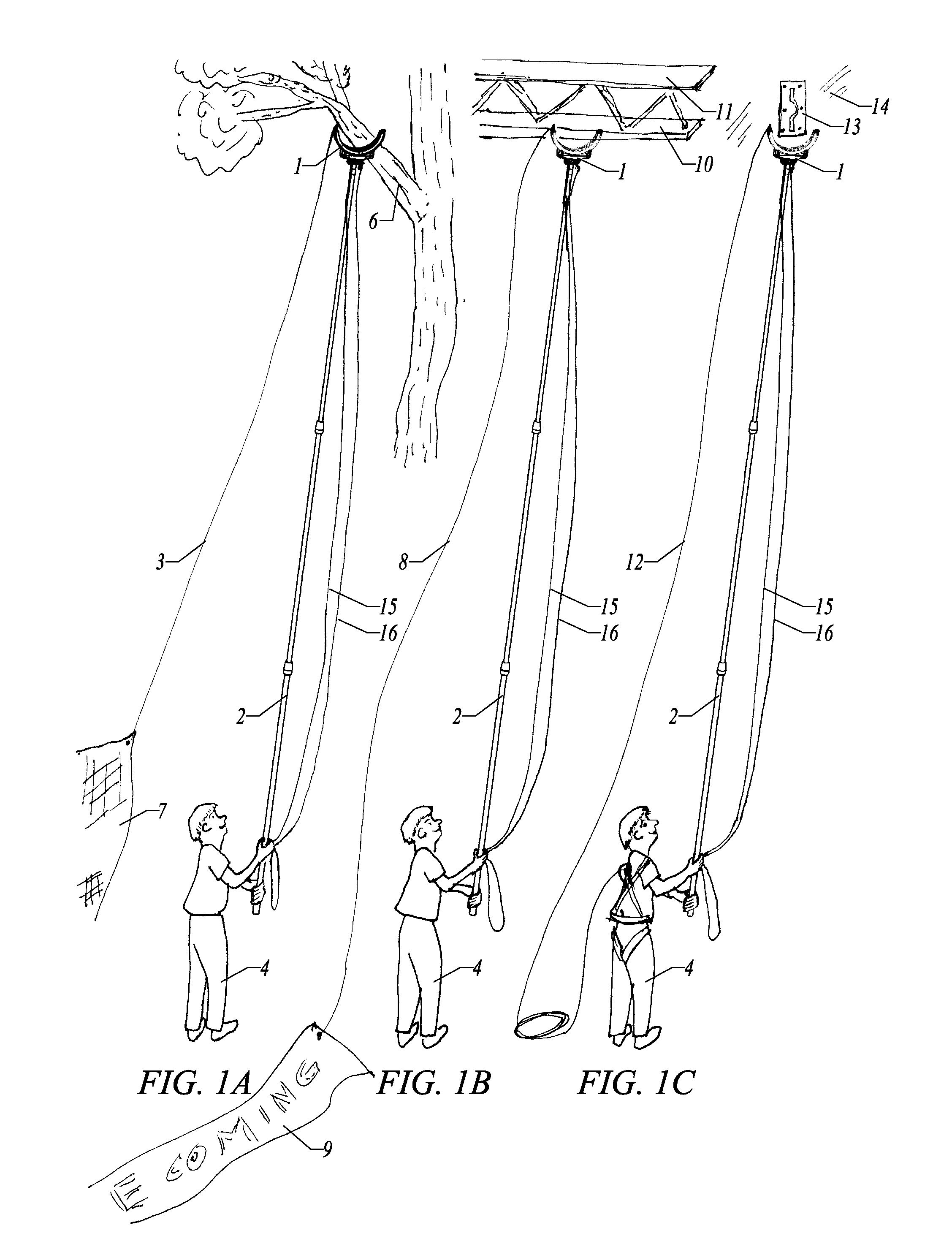
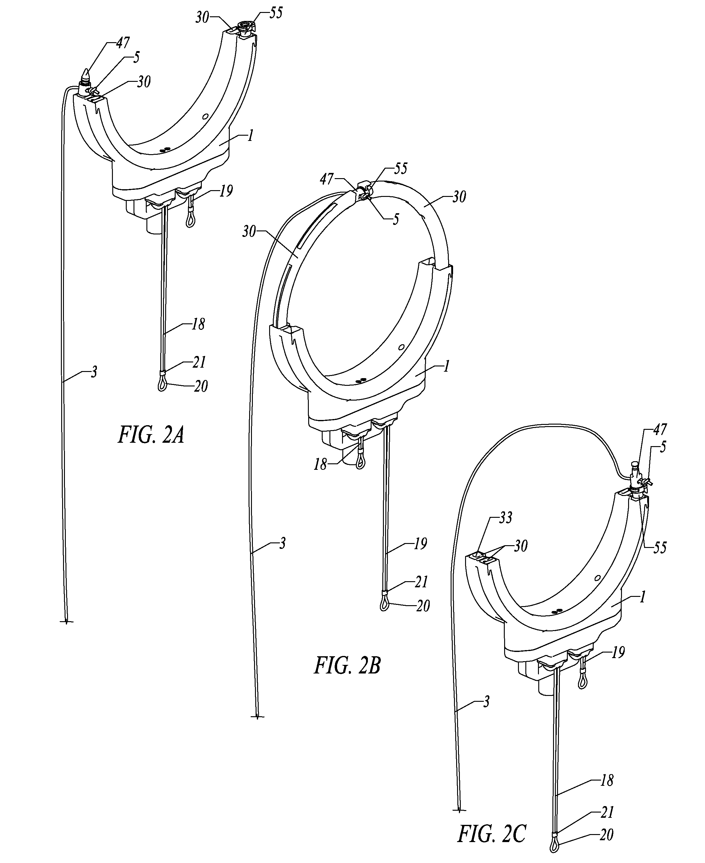
Referring now to the drawings, and in particular, to FIG. 1A, a remotely-operated rope-threading tool 1 is positioned against the underside of an object to be encircled by a rope 3, in this case, a tree limb 6. Because of its light weight, its size and configuration, the rope-threading tool is easily positioned by a person 4 with the aid of a standard extension pole 2. In this illustration, the goal is to thread a supporting rope 3 for a tarp 7 over the tree limb 6 in order to secure the rope 3 with the tarp 7 elevated in the air.

Referring now to FIG. 1B, the example shown is of a person 4 using the threading tool 1 on the extension pole 2 to thread a supporting rope 8 for a banner 9 over a lower member 10 of a roof truss 11 in a building. (The extension pole 2 is shown more clearly in FIG. 12 and FIG. 21.)

Referring now to FIG. 1C, the example shown is of a person 4 using the threading tool 1 on the extension pole 2 to thread a fall-protection rope 12 through a safety ring 13 which ...


PUM


Abstract

A tool for threading a rope through a distant eye or around an object out of reach, such as for elevating tarps into trees, or placing fall protection lines, or securing a distant object. The tool has two curved arms that extend out from the body in unison and converge at a point where the end of the rope is passed from one arm to the other. The arms are then retracted back into the body, pulling the rope through the eye or around the object. The arms are extended by pulling one control line and retracted by pulling a second control line. The tool is typically mounted on the end of a pole, although other mountings are possible. The shape of the tool enables ropes to be threaded through a large number of eye configurations and around objects of varying sizes, even if there are obstructions adjacent the eye.

Description

TECHNICAL FIELDThis invention relates to a device for threading a rope around an object or through an eye. More particularly, it relates to a tool that can be used in many rope-threading applications.BACKGROUND ARTThere are many situations in which it is necessary or advantageous to thread a flexible member (i.e. line, string, cord, rope, cable, etc.) around an object and through the opening it creates (i.e. branch, bar, pole, log, hole, ring, truss, loop, eye, etc.). From here on, we will refer to the flexible member as a rope and the opening as an eye. Often the eye is out of the reach of the person doing the task. This requires the person to physically move to within reach of the eye to thread the rope through and bring the end of the rope back. Another strategy is to tie the end of the rope to a weight and throw the weight through the eye to pull the rope with it, and then the weight with the end of the rope is retrieved.Examples of such tasks include but are not limited to:1) T...

Claims


Application Information

Patent Timeline
Patent Type & Authority Applications(United States)
IPC IPC(8): B25J1/00B63B21/04B65H51/00
CPCA01G23/099A63B29/02B63B21/54F16G11/00B65H51/32B65H57/003B65H51/18
Inventor JANTZEN, LEON KEITH
Owner JANTZEN
Why Eureka
Try Eureka