Eureka AIR delivers breakthrough ideas for toughest innovation challenges, trusted by R&D personnel around the world.

Cutting insert and cutting tool

Active Publication Date: 2013-05-23
TUNGALOY CORP
View PDF13 Cites 31 Cited by
  • Summary
  • Abstract
  • Description
  • Claims
  • Application Information

AI Technical Summary

Benefits of technology

The present invention allows for a cutting insert to be mounted on a tool body with a proper positive axial rake angle and a large cutting edge angle, which enables deep cutting. This results in a more efficient and effective cutting process.

Problems solved by technology

In this way, this cutting insert has the limitation to setting the axial rake angle, and is generally inappropriate for making deep cuts.

Method used


Image

  • Cutting insert and cutting tool
  • Cutting insert and cutting tool
  • Cutting insert and cutting tool

Examples


first embodiment

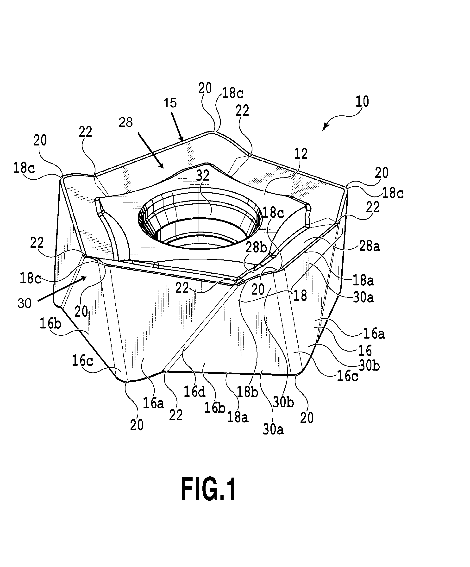
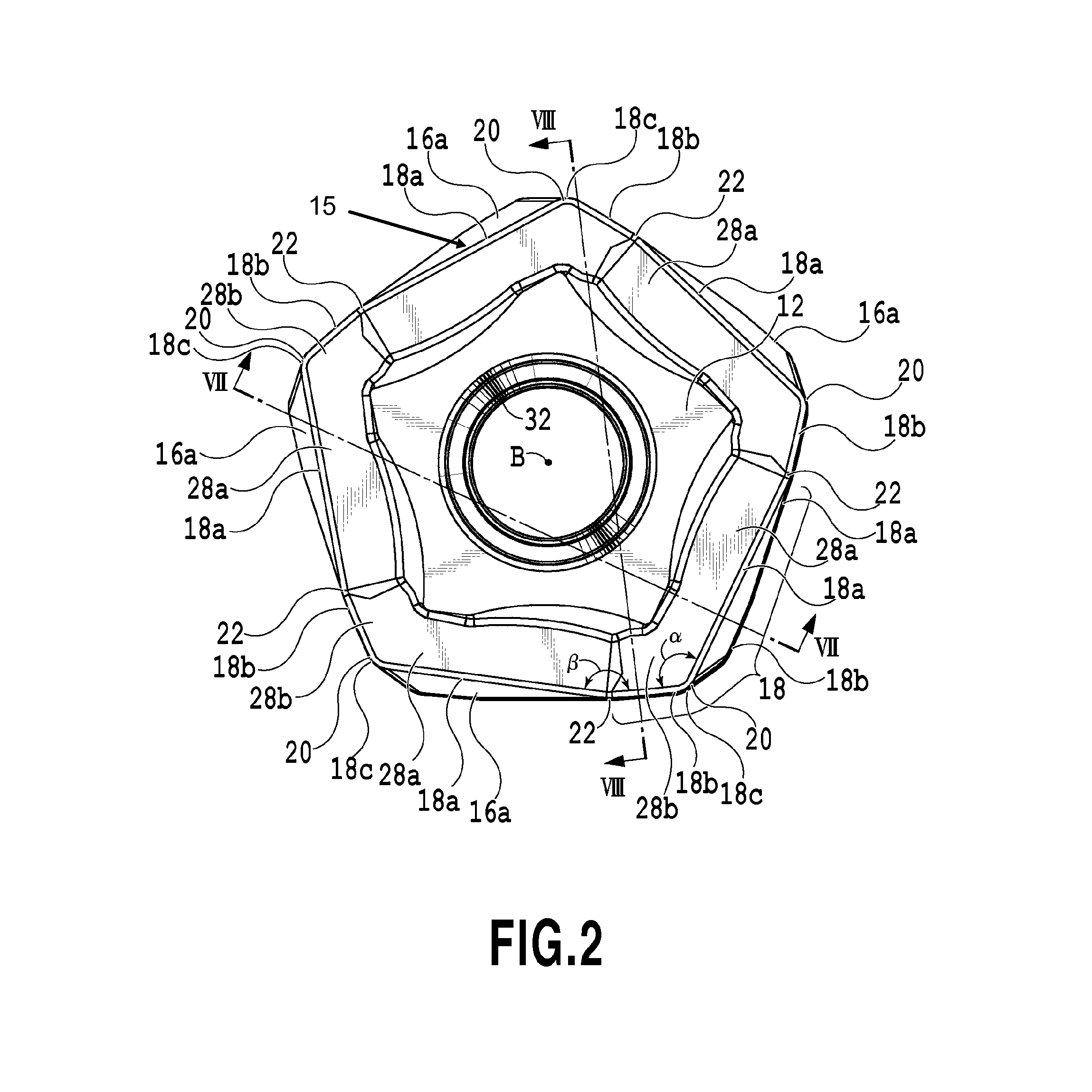
[0075]In each end surface, a portion of each side of a substantial decagon is alternately defined as the first cutting edge 18a and the second cutting edge 18b, the cutting edges being interposed between the corners 20 and 22. Therefore the first cutting edge 18a and the second cutting edge 18b extend in different directions from each first corner 20. It should be noted that the first cutting edge 18a is configured to be capable of acting as the major cutting edge at the time of being mounted on the tool body, and the second cutting edge 18b is likewise configured to be capable of acting as the minor cutting edge at the time of being mounted on the tool body. Particularly in the present first embodiment, the second cutting edge 18b is configured to be capable of acting as a face cutting edge, and in more detail, is configured to be capable of acting as a finishing cutting edge (wiper).

[0076]In addition, when the cutting insert 10 is mounted on the tool body, a rake surface 28 can be...

second embodiment

[0111]In the end surface view (refer to FIG. 16A), two kinds of corners 120 and 122 having different internal corner angles are alternately formed in the end surface. An internal corner angle α of the first corner 120 is smaller than an internal corner angle β of the second corner 122, and herein the internal corner angle β of the second corner 122 is set within a range which is 153° or larger and which is 179° or smaller. The peripheral surface 116 is provided with two kinds of inclination side surfaces 116a and 116b, a first corner side surface 116c extending to connect the first corners 120 of both end surfaces and alternately arranged therebetween, and a second corner side surface 116d likewise extending to connect the second corners 122 of both end surfaces. It should be noted that in the present second embodiment, a width of the second corner side surface 116d is extremely narrow, and is simply illustrated by lines in the figure.

[0112]Each of the first inclination side surface...


PUM


Abstract

A cutting insert is provided with a plurality of cutting portions formed at the intersection portion of each end surface and a peripheral surface. Each cutting portion includes first and second cutting edges. First corners and second corners which differ in their internal angles are alternately formed in each end surface. An internal angle of the first corner is smaller than an internal angle of the second corner. Each first cutting edge has a portion extending to approach the median plane as a distance from a corresponding first corner increases. A first side surface portion extending on the peripheral surface from each first cutting edge forms an insert internal obtuse angle, and a second side surface portion extending on the peripheral surface from each second cutting edge forms an insert internal acute angle.

Description

CROSS-REFERENCE TO RELATED APPLICATIONS[0001]This application is a continuation-in-part of PCT application No. PCT / JP2011 / 072111 filed Sep. 27, 2011, which published as WO 2012 / 043579A1 and claims the benefit of Japanese Patent Application No. 2010-214801, filed Sep. 27, 2010. The contents of the aforementioned applications are incorporated by reference in their entirety.BACKGROUND OF THE INVENTION[0002]1. Field of the Invention[0003]The present invention relates to a cutting insert and a cutting tool, and particularly, to a cutting insert used in an indexable cutting tool and a cutting tool in which the cutting insert is detachably mounted on a tool body.[0004]2. Description of the Related Art[0005]An example of a cutting insert and a cutting tool is disclosed in WO2008 / 120186. The cutting insert mounted on a tool body described in WO2008 / 120186 is formed in a substantially hexagonal plate shape, and is equipped with two same opposing end surfaces and a peripheral surface extending...

Claims


Application Information

Patent Timeline
IPC IPC(8): B23C5/20B23B27/16
CPCB23B27/007Y10T407/1906B23B2200/0409B23B2200/0447B23B2200/202B23B2200/204B23C5/06B23C5/207B23C2200/0444B23C2200/125B23C2200/203B23C2200/205B23C2200/208B23B27/1607B23B27/1611B23C5/205B23C2200/201Y10T407/22Y10T407/2268Y10T407/23B23B27/145B23C5/202
Inventor BHAGATH, KEDAR SURESHYAMAGUCHI, TAKASHI
Owner TUNGALOY CORP
Why Eureka
Eureka Blog
Learn More