Insert-exchangeable rotary tool and throwaway insert

a rotary tool and insert technology, applied in the field of insert-exchangeable rotary tools and insert-exchangeable insert-exchangeable insert-exchangeable insert-exchangeable insert-exchangeable insert-exchangeable insert-exchangeable insert-exchangeable insert-exchangeable insert-exchangeable insert-exchangeable insert-exchangeable insert-exchangeable insert-exchangeable insert-exchangeable insert-exchangeable insert-exchangeable insert-exchangeabl

Inactive Publication Date: 2003-01-02
HITACHI TOOL ENG LTD
View PDF3 Cites 20 Cited by
  • Summary
  • Abstract
  • Description
  • Claims
  • Application Information

AI Technical Summary

Benefits of technology

[0007] Accordingly, an object of the present invention is to provide an insert-exchangeable, rotary tool such as a face-milling tool, which can be operated at a high feed while keeping high precision, and can stably cut works suffering from large variations of cutting conditions such as works with many holes, pre-hardened steel, etc.
[0008] Another object of the present invention is to provide a throwaway insert used for such an insert-exchangeable, rotary tool, which has a long life and excellent crack resistance.
[0009] As a result of intense research in view of the above objects, the inventors have found that by attaching substantially square-shaped throwaway inserts comprising flanks each having a flat surface portion in a substantially center portion to an insert-exchangeable, rotary tool, such that a radial rake is negative, and that a major cutting edge formed by an outward curved edge line circularly extends from a lowermost point toward a periphery of the tool, impact applied to the throwaway inserts is eased in a cutting process, thereby achieving high-feed cutting and a long life even with intermittent cutting.
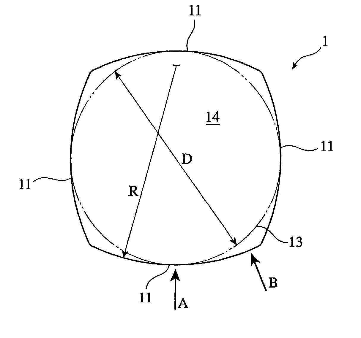
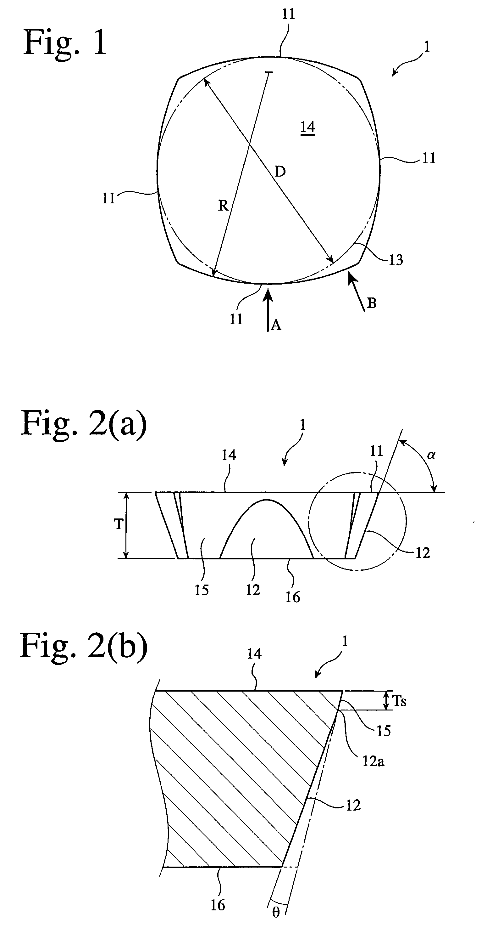
[0044] The circular cutting edge 11 has a radius of curvature R preferably 0.6-1.6 times the diameter D of an inscribed circle 13 in the insert 1. When R / D is less than 0.6 times, the insert 1 has substantially the same shape as a round insert, resulting in a large cutting edge angle in applications with a large cutting depth, thereby making it impossible to carry out cutting at a high feed. To make the cutting depth larger with a cutting edge angle unchanged, the inscribed circle 13 should be increased. When R / D is more than 1.6 times, the cutting edge 11 has substantially the same shape as a straight cutting edge, losing the advantages of the curved cutting edge, which are a long life because of long contact length between the cutting edge 11 and a work during cutting, a high strength in intermittent cutting, and high resistance to breakage even when heat cracking occurs because of a compression force during cutting.
[0049] The inventors have investigated the mechanism of generating impact to the insert 1 in a cutting process, separately on (1) impact when the insert 1 starts to bite the work W (at the start of cutting), (2) impact during a period from engagement to the work W to separation therefrom. As a result, the inventors have found that the impact (1) can be reduced by causing the lowermost point 7 of an outward curved major cutting edge 11 as a starting point of cutting to shallowly bite into a work W, and the impact (2) can be reduced by providing a negative radial rake Rr. With the insert-exchangeable, rotary tool of the present invention having these features, chips 8 generated by contact with the work W at the initial stage of cutting are thin and become gradually thicker as the tool rotates, as shown in FIG. 7. Thus, a large impact force is not applied to the tool, enabling the high feed of the tool and stable intermittent cutting with a long life of throwaway inserts 1.

Problems solved by technology

However, because the side surface of the insert is a curved surface, precise positioning is difficult, needing an edge position-controlling screw.
Further, because the round insert is attached inclined in two directions, the insert is likely to rotate during cutting, resulting in the likelihood that the edge position deviates.
Accordingly, this tool is suitable for working at a cutting depth of as small as 0.1-1 mm or less, and if the tool is designed bigger for deeper cutting, an edge engaged to cutting becomes too long, resulting in too large cutting resistance.
It has been found, however, that this high-feed, throwaway-type, rotary tool is not necessarily satisfactory to achieve a higher feed per one tooth.
In addition, because this throwaway insert 301 has circular major cutting edges 311 on two opposing surfaces with two other flat opposing surfaces for abutting the tool, it is not economically advantageous.

Method used


Image

  • Insert-exchangeable rotary tool and throwaway insert
  • Insert-exchangeable rotary tool and throwaway insert
  • Insert-exchangeable rotary tool and throwaway insert

Examples


examples 5-8

[0079] The same effect was obtained, with a major cutting edge 11 consisting of a curved line extending from the lowermost point 7 toward the periphery and a straight line as shown in FIG. 21 (Example 5), with a major cutting edge 11 consisting of a plurality of straight lines from around the lowermost point 7 toward the periphery at a cutting edge angle .kappa. of 35.degree. or less as shown in FIG. 22 (Example 6), with a negative radial rake Rr changed intermittently as shown in FIG. 23 (Example 7), or with a radial rake Rr changed smoothly and continuously with a convex upper surface of an insert (Example 8). This effect is widely obtained ranging from a small diameter to a large diameter regardless of the diameter of cutting tool edge.

[0080] As described above in detail, the insert-exchangeable, rotary tool such as a face-milling tool, etc. equipped with the throwaway insert of the present invention can cut a work efficiently at a high feed, with a long life because of improved ...


PUM

PropertyMeasurementUnit
cutting edge angleaaaaaaaaaa
Diameteraaaaaaaaaa
] Angleaaaaaaaaaa

Abstract

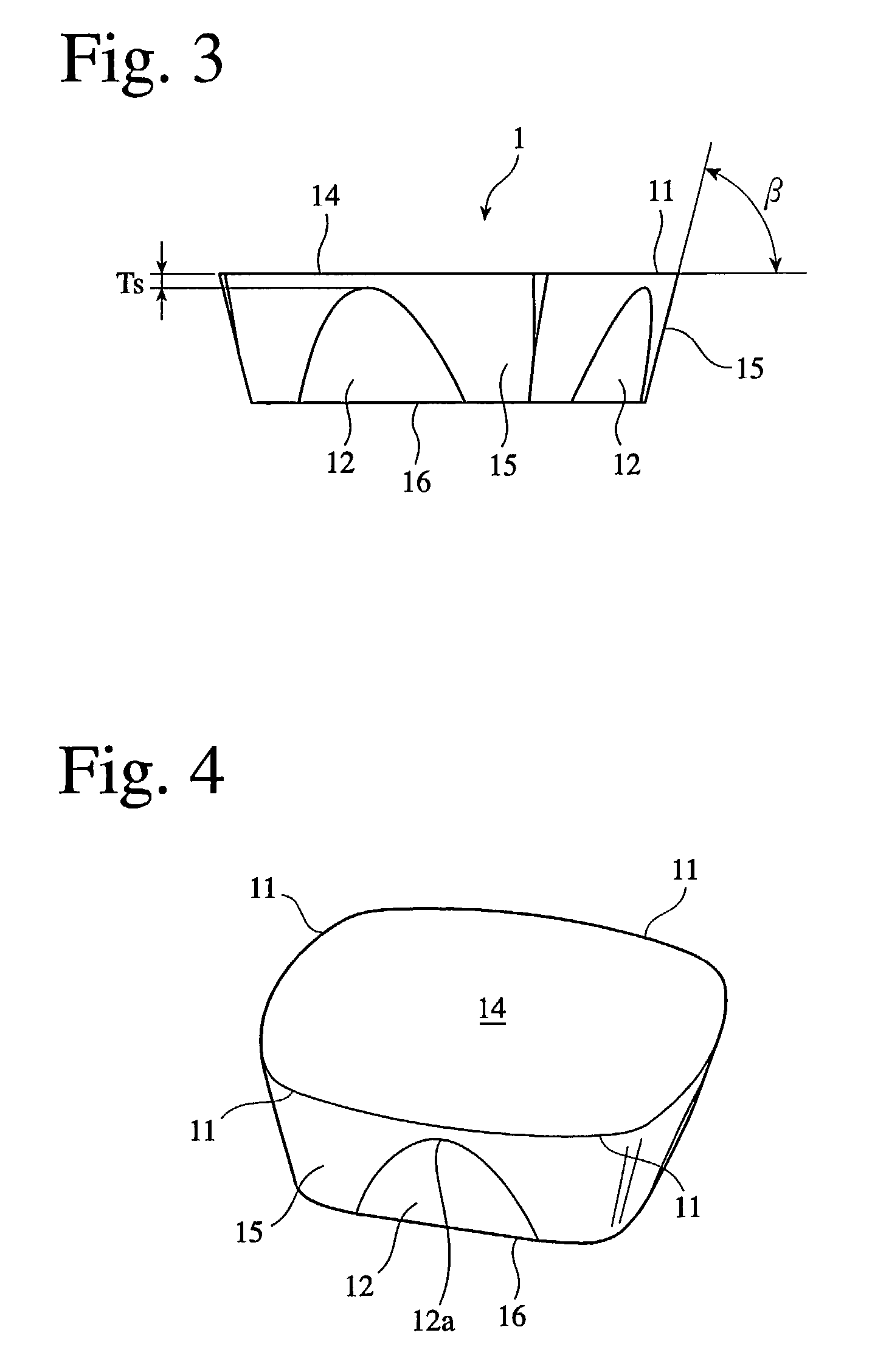
An insert-exchangeable, rotary tool to which throwaway inserts are detachably attached, the insert comprising substantially square-shaped face and bottom surface and an outward curved flank on each side surface, and having a positive-type shape in which an outward curved edge line formed by the face and the flank serves as a cutting edge; each flank having in a substantially center portion a flat surface portion extending to the bottom surface without contacting with the cutting edge; a major cutting edge formed by the outward curved edge line circularly extending from its lowermost point toward a periphery of the tool when the insert is attached to the insert-exchangeable, rotary tool, such that it has a negative radial rake; and the lowermost point being positioned inward a center of the outward curved major cutting edge.

Description

[0001] The present invention relates to an insert-exchangeable, rotary tool such as a face-milling tool, etc. suitable for high-feed working, and throwaway insert used therein.[0002] As an insert-exchangeable, rotary tool suitable for high feed, Japanese Patent Laid-Open No. 2000-126920 discloses a face-milling cutter equipped with circular throwaway inserts. This face-milling cutter comprises round throwaway inserts each having a mounting hole at a center, cylindrical holders each having at a tip end a supporting seat for fixing the round throwaway insert by a flat head screw in such a direction that its upper surface serves as a flank and its side surface serves as a face, a cutter body for fixing the cylindrical holders, and wedges each inserted into a plurality of circular holes provided in a peripheral portion of a front surface of the cutter body in parallel with its axis and pressed into a gap between a flat surface provided on a periphery of each cylindrical holder and the c...

Claims


Application Information

Patent Timeline
Patent Type & Authority Applications(United States)
IPC IPC(8): B23C5/20
CPCB23C5/06B23C5/202B23C2200/125B23C2200/203Y10T407/23B23C2210/045Y10T407/1908Y10T407/192B23C2210/0435B23C5/20
Inventor NAGASHIMA, YOSHIMITSU
Owner HITACHI TOOL ENG LTD
Why Eureka
Try Eureka