

Apparatus and method for high-frequency operation in a battery charger
a battery charger and high-frequency technology, applied in the field of industrial and motor vehicle battery chargers, can solve the problems of reducing the efficiency of battery chargers operating at ac mains frequency, reducing the efficiency of battery chargers, and being larger and heavier than desired. , to achieve the effect of reducing the size and weight of battery chargers and achieving higher operating efficiency
- Summary
- Abstract
- Description
- Claims
- Application Information
AI Technical Summary
Benefits of technology
Problems solved by technology
Method used
Image

Examples
Embodiment Construction
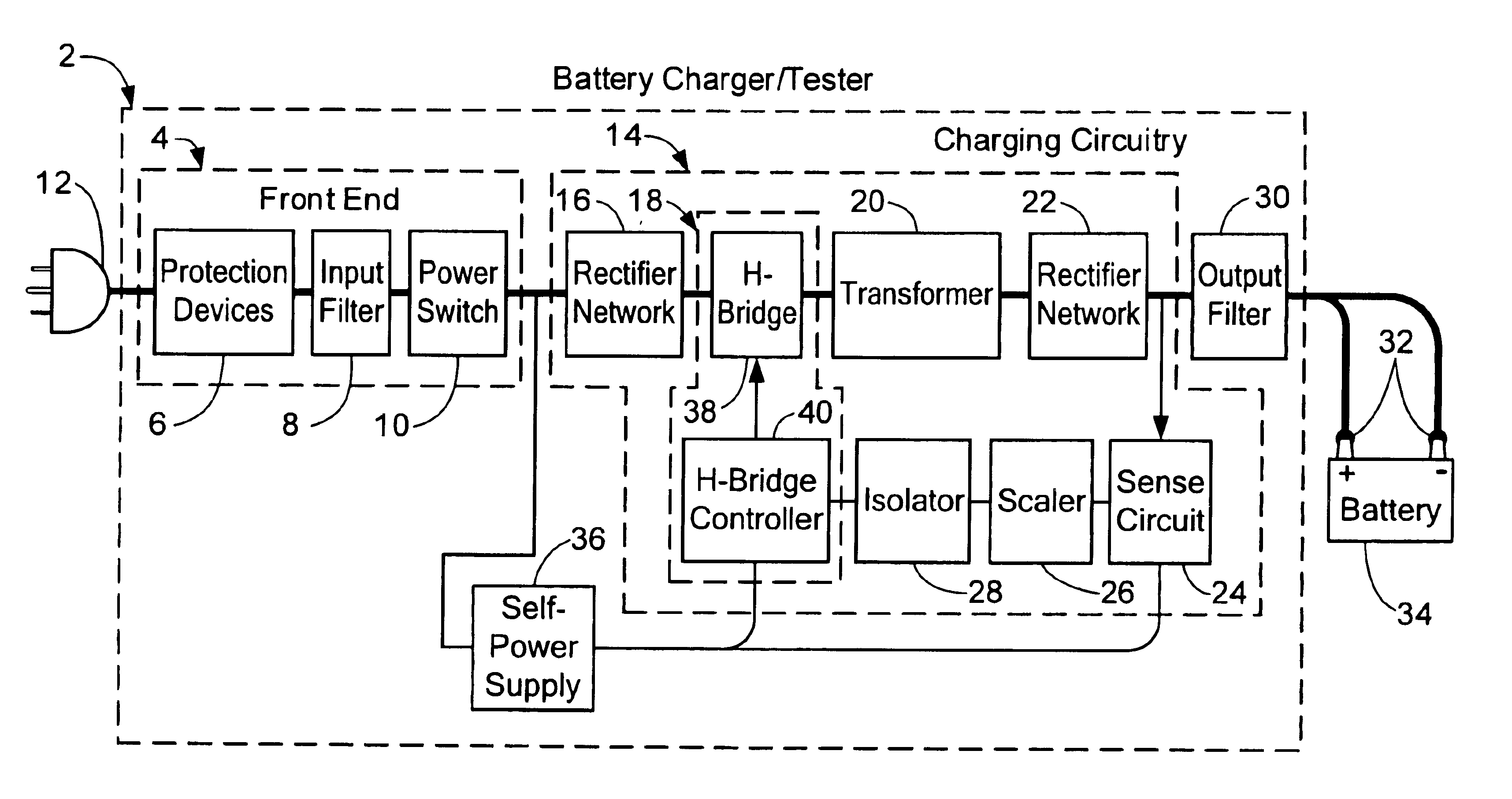
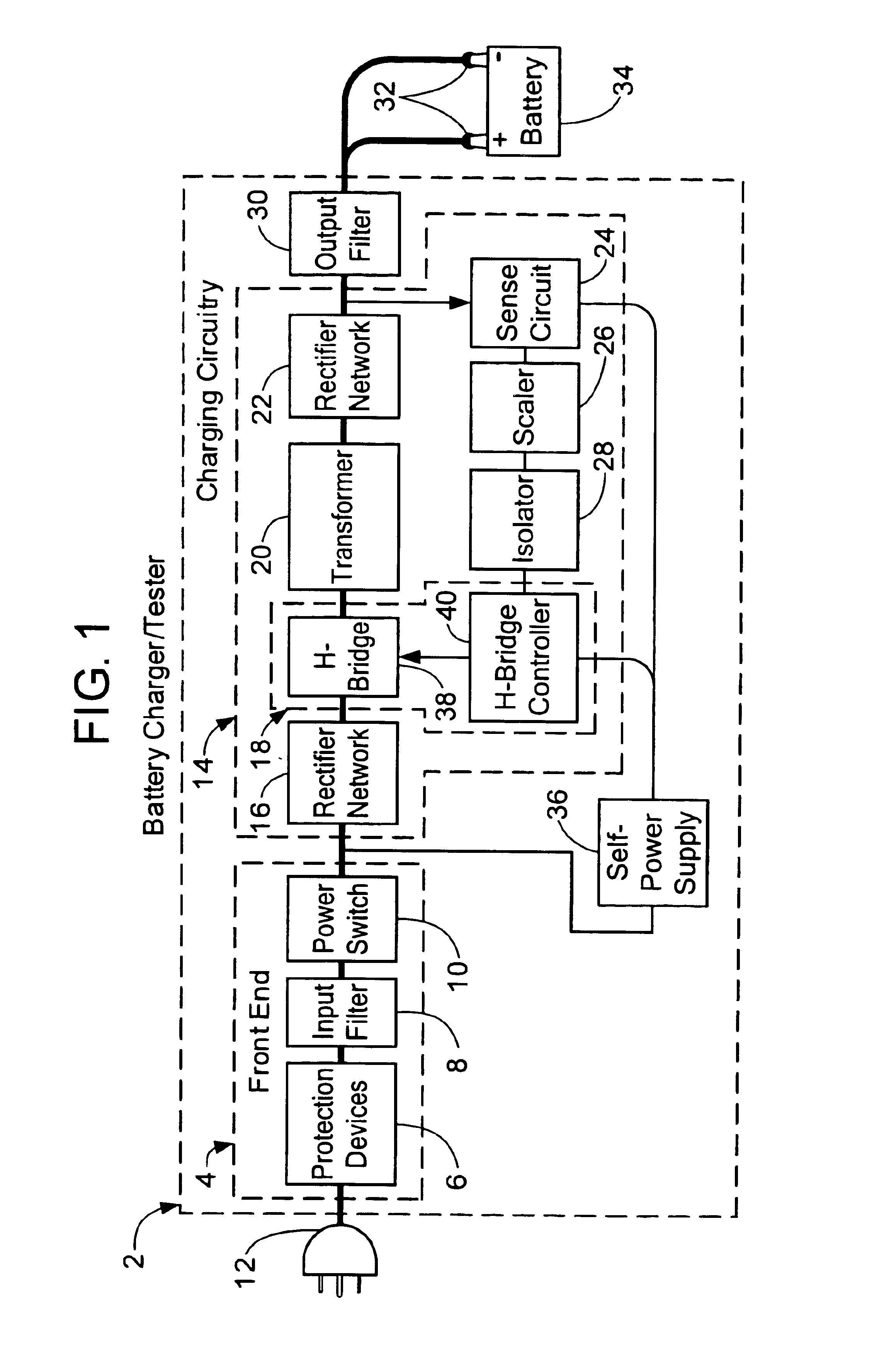
A battery charger includes line-level input rectification, a high-frequency oscillator-controlled chopper circuit, multiple transformers operating in parallel, and controlled output rectification. Use of line-level input rectification reorders the elements of the battery charger compared to previous designs. A chopper frequency several orders of magnitude higher than that of the AC power mains is used. The use of multiple, parallel-wired transformers for voltage and current transformation eases constraints on the physical geometry of a manufactured battery charger product by permitting individual transformers, each smaller than a comparable single transformer, to be employed. Controlled output rectifiers permit power levels to be regulated dynamically.
A preferred embodiment of the present inventive apparatus and method is shown in FIG. 1. Within a battery charger 2, a front-end circuit 4, comprised of a protection device 6, an electromagnetic interference (EMI) filter 8, and a main ...
PUM
| Property | Measurement | Unit |
|---|---|---|
| frequency | aaaaa | aaaaa |
| frequency | aaaaa | aaaaa |
| electrical | aaaaa | aaaaa |
Abstract
Description
Claims
Application Information