Dielectric lens, dielectric lens device, design method of dielectric lens, manufacturing method and transceiving equipment of dielectric lens

Inactive Publication Date: 2006-09-14
MURATA MFG CO LTD
View PDF6 Cites 62 Cited by
  • Summary
  • Abstract
  • Description
  • Claims
  • Application Information

AI Technical Summary

Benefits of technology

[0031] According to such a configuration, dust, rain, and snow do not collect in the recessed portion formed by the front-side refraction face and the

Problems solved by technology

Although reduction in weight was realized, a reduction in thickness could not be realized with lenses in which the surface side was convex.
Also, when attempting to reduce the thickness of a lens in which the surface side has a convex shape by subjecting the surface side thereof to zoning, the conventional techniques simply cut off the front side, such as with the Fresnel lens serving as an optical lens, or as shown in FIG. 4C, so ther

Method used


Image

  • Dielectric lens, dielectric lens device, design method of dielectric lens, manufacturing method and transceiving equipment of dielectric lens
  • Dielectric lens, dielectric lens device, design method of dielectric lens, manufacturing method and transceiving equipment of dielectric lens
  • Dielectric lens, dielectric lens device, design method of dielectric lens, manufacturing method and transceiving equipment of dielectric lens

Examples


first embodiment

[0063] Description will be made regarding a dielectric lens, design method and manufacturing method thereof with reference to FIG. 5A through FIG. 9.

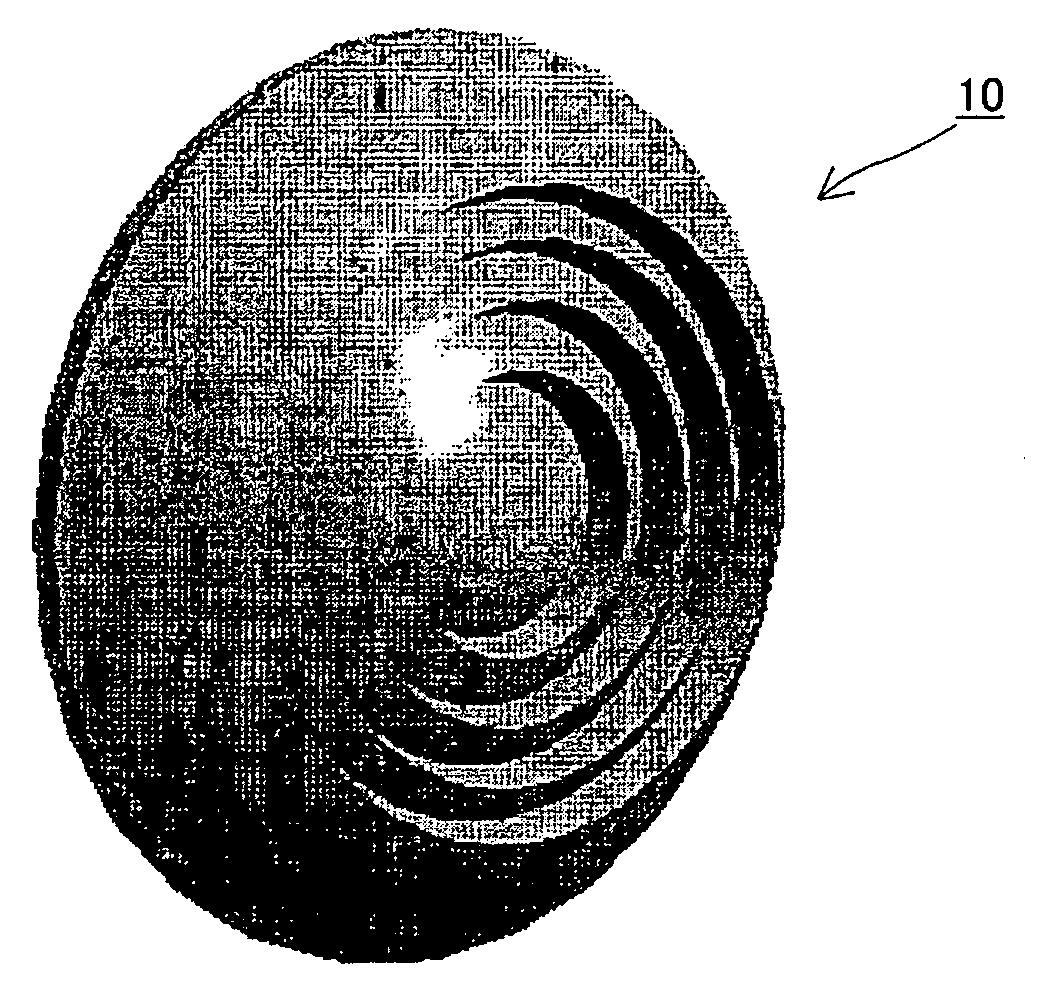
[0064]FIG. 5A is an external perspective view of a dielectric lens, and FIG. 5B is a cross-sectional view at a face including the optical axis thereof. Now, let us say that the z axis is taken as the optic-axis direction, the x axis is taken as the radial direction, where the positive direction of z is the surface direction of the dielectric lens, and the negative direction of z is taken as the rear-face direction of the dielectric lens. The rear-face side of this dielectric lens 10 is the side facing a primary radiator. The dielectric portion 1 of the dielectric lens 10 consists of a uniform substance with a greater specific inductive capacity than the ambient medium (air) through which electromagnetic waves are propagated. The surface of the dielectric lens 10 comprises front-side refraction faces Sr, and stepped faces Sc which conne...

second embodiment

[0119] Next, a description will be made regarding a dielectric lens and the design method thereof, with reference to FIG. 10A through FIG. 12C.

[0120]FIG. 10A is a cross-sectional view of the principal portions on the surface of the dielectric lens including the optical axis, designed by the processing from step S1 through step S6 in FIG. 7. With the above-mentioned processing alone, z is reduced while fixing x so that the light path length is shortened by one wave length when z of the coordinates (z, x) on the surface of the lens reaches the upper limit zm, so the stepped faces Sc (Sc1-Sc4) become faces parallel to the optical axis. With such a shape, sharply pointing portions (valley V and mountain T) are formed on the boundary of the refraction face and the stepped face. Accordingly, the inclination angles of the stepped faces Sc (Sc1-Sc4) are corrected as described next.

[0121]FIG. 10B is a cross-sectional view of the principal portions on the surface including the optical axis ...

third embodiment

[0126] Next, description will be made regarding a dielectric lens and the design method thereof with reference to FIG. 13A through FIG. 15B.

[0127] This third embodiment shows an example of change of the shape of the dielectric lens when changing aperture distribution. FIG. 14 illustrates an example of three types of aperture distribution. FIGS. 12A, 12B and 12C illustrate the shape of the dielectric lens where three aperture distributions in FIG. 14 were given and designed. FIGS. 15A, 15B and 15C correspond to FIGS. 14A, 14B and 14C respectively. The aperture distributions of FIG. 14 are all the parabolic taper distributions shown in Expression (4), with parameters c and n changing. Each example shown in FIG. 13 is an example of the four-step zoning in which steps occur in four places, wherein the closer to a convex shape the surface side of the dielectric lens is, the closer to uniformity the aperture distribution is, but conversely, the closer to a convex shape the rear face side...


PUM


Abstract

A design process first determines a desired aperture distribution, then converts the electric power conservation law, Snell's law on the rear face side of a dielectric lens, and the formula representing light-path-length constraint, into simultaneous equations, and computes the shapes of the surface and rear face of the dielectric lens depending on the azimuthal angle θ of a primary ray from the focal point of the dielectric lens to the rear face of the dielectric lens, and then reduces the light path length in the formula showing light-path-length constraint by an integral multiple of the wavelength when the coordinates on the surface of the dielectric lens reach a predetermined restriction thickness position. A dielectric lens is designed by sequentially changing the lazimuthal angle θ from its initial value, and also repeating the second and third steps. Thus, downsizing and quantification is realized by zoning while keeping antenna properties at the time of constituting a dielectric lens antenna in a good condition.

Description

[0001] This is a continuation of PCT / JP2004 / 008346. TECHNICAL FIELD [0002] The present invention relates to a dielectric lens used in a dielectric lens antenna in a microwave band or millimeter wave band, a dielectric lens device, a design method of a dielectric lens, a manufacturing method of a dielectric lens and transceiving equipment which uses a dielectric lens or a dielectric lens device. BACKGROUND ART [0003] A dielectric lens antenna used in a microwave or millimeter wave band is for refracting an electromagnetic wave which radiates widely from a primary radiator well, aligning the phase thereof on a virtual aperture face ahead of a lens, and also creating an electromagnetic field amplitude distribution on the aperture face thereof. Thus, the electric wave can be made to emit sharply in a certain direction. This dielectric lens antenna resembles a lens used for optics, but the greatest difference is that it is necessary not only to simply align the phase but also to create a...

Claims


Application Information

Patent Timeline
IPC IPC(8): H01Q15/08H01Q15/02
CPCH01Q15/08
Inventor NAGAI, TOMOHIRO
Owner MURATA MFG CO LTD
Why Eureka
Try Eureka