
Method and apparatus for designing and manufacturing electronic circuits subject to process variations

a technology of process variation and electronic circuit, applied in the direction of program control, specific program execution arrangement, detecting faulty computer hardware, etc., can solve problems such as unpredictability, and achieve the effect of reducing worst-case design margins, allowing unpredictability of behaviour, and substantial freedom for run-time controllers

Active Publication Date: 2005-10-20
INTERUNIVERSITAIR MICRO ELECTRONICS CENT (IMEC VZW)
View PDF23 Cites 38 Cited by
  • Summary
  • Abstract
  • Description
  • Claims
  • Application Information

AI Technical Summary

Benefits of technology

The present invention provides a method and device for improving the design of electrical circuits, especially digital circuits, by using a design-time run-time separation approach. This approach allows for a more robust design that can operate effectively even when there are uncertainties in the manufacturing process. The invention also includes a method for selecting the best performing working points for a circuit based on actual performance data and cost parameters. This helps to avoid worst-case scenarios and ensures that the circuit operates correctly. The invention also includes a program storage device and a system-level functionality check to ensure that the entire application is working correctly. Overall, the invention provides a more efficient and effective way to design and manufacture electrical circuits.

Problems solved by technology

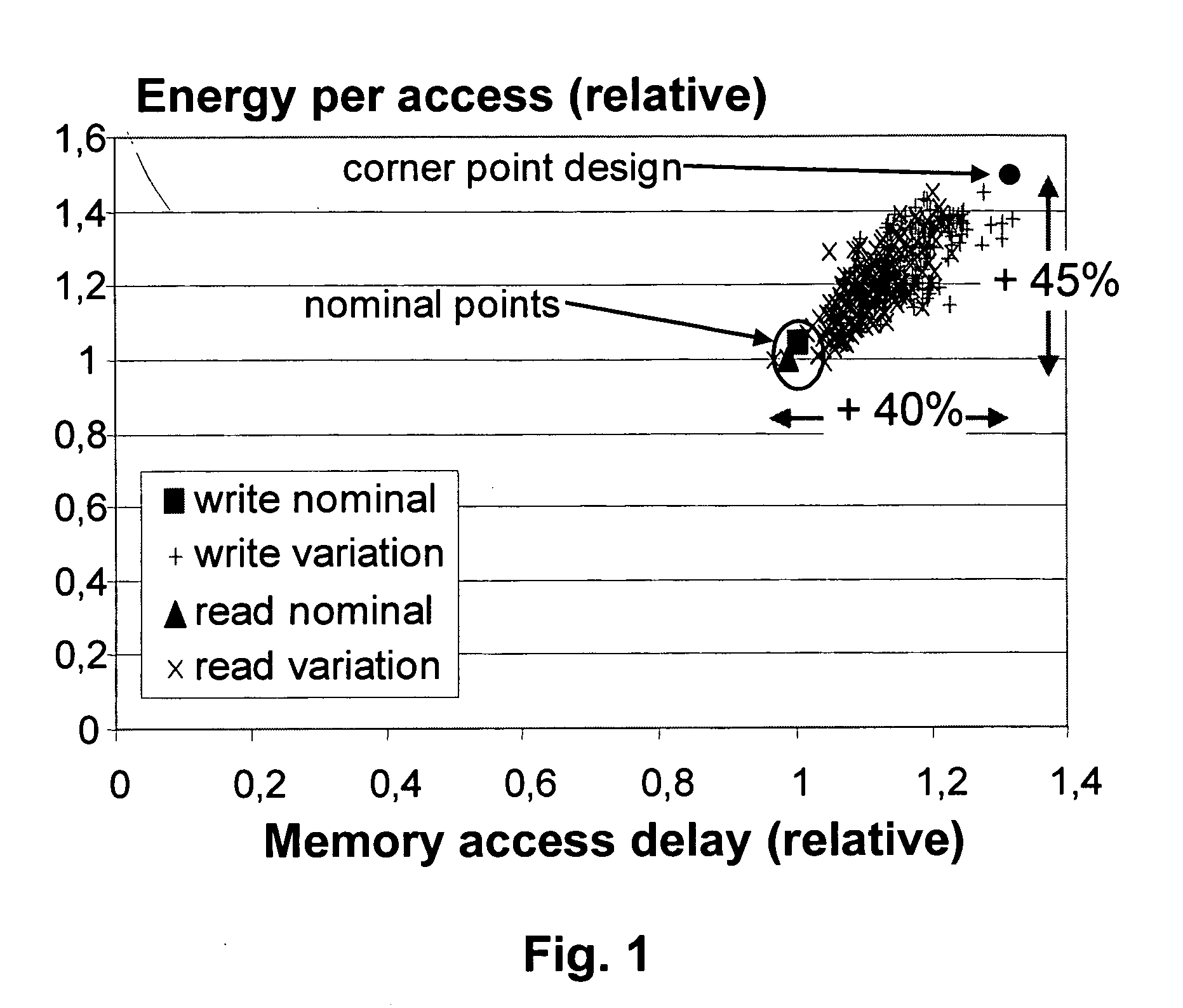
For example, process variations in the manufacture of the actual circuit can be the cause of an unpredictable behaviour at run time

Method used


Image

  • Method and apparatus for designing and manufacturing electronic circuits subject to process variations
  • Method and apparatus for designing and manufacturing electronic circuits subject to process variations
  • Method and apparatus for designing and manufacturing electronic circuits subject to process variations

Examples


Embodiment Construction

[0111] The present invention will be described with respect to particular embodiments and with reference to certain drawings but the invention is not limited thereto but only by the claims. The drawings described are only schematic and are non-limiting. In the drawings, the size of some of the elements may be exaggerated and not drawn on scale for illustrative purposes. The dimensions and the relative dimensions do not correspond to actual reductions to practice of the invention.

[0112] The terms first, second, third and the like in the description and in the claims, are used for distinguishing between similar elements and not necessarily for describing a sequential or chronological order. It is to be understood that the terms so used are interchangeable under appropriate circumstances and that the embodiments of the invention described herein are capable of operation in other sequences than described or illustrated herein.

[0113] It is to be noticed that the term “comprising”, used...


PUM


Abstract

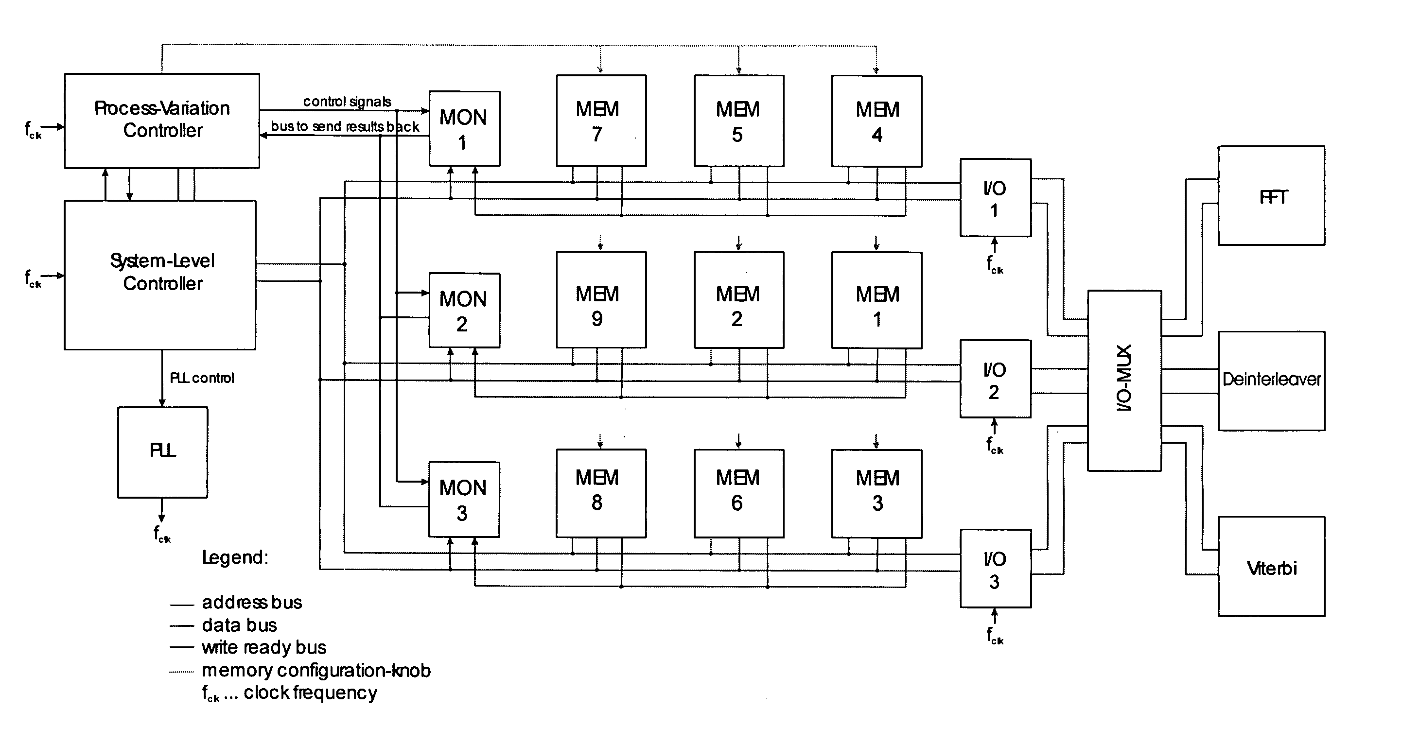
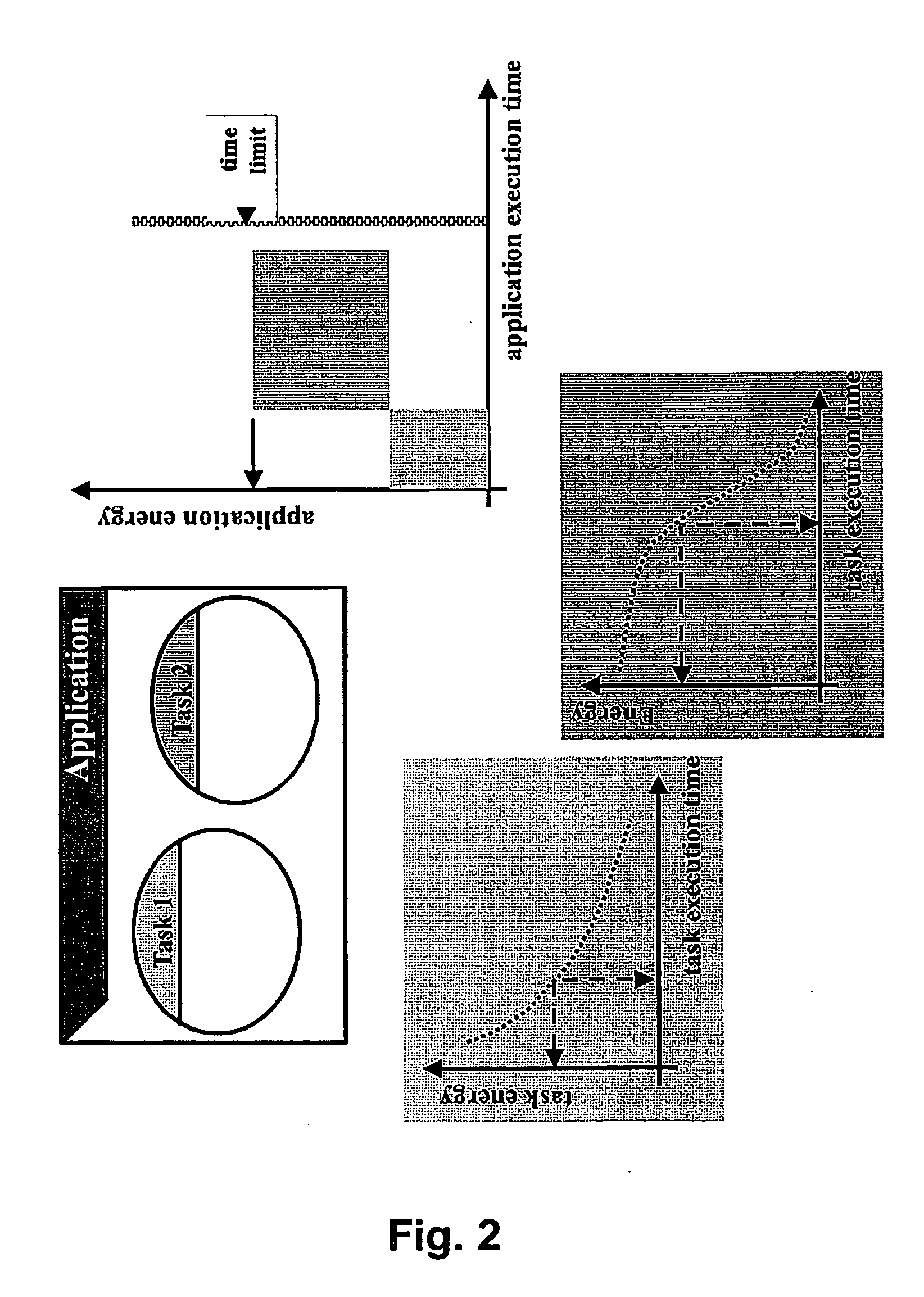
Methods and apparatus are described in which, at design-time a thorough analysis and exploration is performed to represent a multi-objective “optimal” trade-off point or points, e.g. on Pareto curves, for the relevant cost (C) and constraint criteria. More formally, the trade-off points may e.g. be positions on a hyper-surface in an N-dimensional Pareto search space. The axes represent the relevant cost (C), quality cost (Q) and restriction (R) criteria. Each of these working points is determined by positions for the system operation (determined during the design-time mapping) for a selected set of decision knobs (e.g. the way data are organized in a memory hierarchy). The C-Q-R values are determined based on design-time models that then have to be “average-case” values in order to avoid a too worst-case characterisation. At processing time, first a run-time BIST manager performs a functional correctness test, i.e. checks all the modules based on stored self-test sequences and “equivalence checker” hardware. All units that fail are deactivated (so that they cannot consume any power any more) and with a flag the run-time trade-off controllers, e.g. Pareto controllers, are informed that these units are not available any more for the calibration or the mapping. At processing time, also a set of representative working points are “triggered” by an on-chip trade-off calibration manager, e.g. a Pareto calibration manager, that controls a set of monitors which measure the actual C-Q-R values and that calibrates the working points to their actual values. Especially timing monitors require a careful design because correctly calibrated absolute time scales have to be monitored.

Description

RELATED APPLICATIONS [0001] This patent application claims the benefit of U.S. Provisional Application No. 60 / 612,427, filed Sep. 23, 2004, which is hereby incorporated by reference in its entirety.BACKGROUND OF THE INVENTION [0002] 1. Field of the Invention [0003] The invention relates to design methodologies for electrical systems, more in particular electrical circuits (especially digital circuits), to circuitry designed with said methodologies and to circuit parts, specially designed and incorporated within said digital circuits to enable operation of said circuits in accordance with the proposed concepts. [0004] 2. Description of the Related Art [0005] Technology scaling has historically improved the performance of embedded systems, both in energy consumption and in speed. Scaling minimum feature sizes below 100 nm however, brings a host of problems, which cannot be completely solved at technology level. Back-end performance degradation, increased leakage currents and increased...

Claims


Application Information

Patent Timeline
Patent Type & Authority Applications(United States)
IPC IPC(8): G06F17/50G06F19/00
CPCG06F17/5045G06F30/30
Inventor PAPANIKOLAOU, ANTONISMIRANDA, MIGUELCATTHOOR, FRANCKYWANG, HUA
Owner INTERUNIVERSITAIR MICRO ELECTRONICS CENT (IMEC VZW)
Learn More