Magnetic shimming configuration with optimized turn geometry and electrical circuitry

a technology of electrical circuitry and magnetic shimming, applied in the direction of magnetic bodies, instruments, using reradiation, etc., can solve the problems of affecting the electrical circuitry of the axis, creating a magnetic field that is not completely uniform, etc., to improve the conductor structure, improve the electrical circuitry, and optimize the turn geometry

Inactive Publication Date: 2008-09-23
FLORIDA STATE UNIV RES FOUND INC
View PDF7 Cites 17 Cited by
  • Summary
  • Abstract
  • Description
  • Claims
  • Application Information

AI Technical Summary

Benefits of technology

[0023]The present invention is a magnetic shimming configuration for a high-field magnet having an improved conductor structure, optimized turn geometry and improved electrical circuitry. The present invention accomplishes this by combining the corrective functionalities of the standard X and ZX shims into two single, simplified electrical circuits and conductors, optimized for field strength as a function of turn location. The standard Y and ZY shims were also replaced with two single, simplified circuits and conductors that are corrective of the Y and ZY fields. The new configuration also eliminates the need of additional “second, outboard turns” of the traditional X, ZX, Y, and ZY shims, located further away from the mid-plane.

Problems solved by technology

A typical high-field magnet creates a magnetic field that is not completely uniform.
However, since the current in the two pair of loops flows in opposite directions, these off-axis components tend to be cancelled out.

Method used


Image

  • Magnetic shimming configuration with optimized turn geometry and electrical circuitry
  • Magnetic shimming configuration with optimized turn geometry and electrical circuitry
  • Magnetic shimming configuration with optimized turn geometry and electrical circuitry

Examples


Embodiment Construction

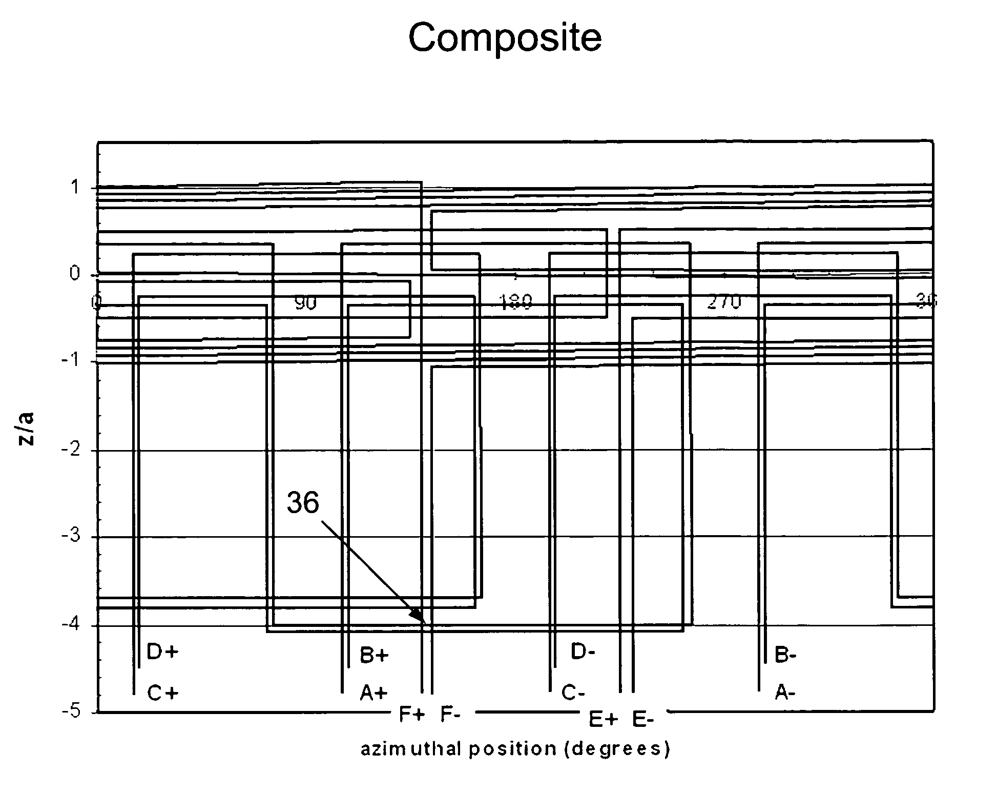
[0043]The present invention is a magnetic shimming configuration having optimized turn geometry and electrical circuitry for correcting spatial inhomogeneities of a magnetic field. The proposed shim configuration is illustrated in FIGS. 9-16. Circuits A and B (which replace the prior art X and ZX shim configurations) are illustrated in FIGS. 9 and 10, respectively. FIG. 9 shows Circuit A, which is an “X+ZX” shim.

[0044]The arrows shown in FIG. 9 depict the direction of current flow (true of all the drawing figures). The reader will observe that Circuit A includes one complete loop surrounding the −x axis. The azimuthal plot shows this complete loop, which is centered on the 180 degree position. When viewed on the azimuthal plot, current in this loop flows in a clockwise direction. Circuit A replaces the inboard, above-midplane turns of the X and ZX shims of the prior art.

[0045]FIG. 10 shows Circuit B. It follows the same path as Circuit A, except that it is translated in the −z direc...


PUM

PropertyMeasurementUnit
radiusaaaaaaaaaa
radiusaaaaaaaaaa
currentaaaaaaaaaa

Abstract

A magnetic shimming configuration for a high-field magnet having optimized turn geometry and electrical circuitry. The present invention accomplishes this by combining the corrective functionalities of the standard X and ZX shims into two single, simplified electrical circuits and conductors, optimized for field strength as a function of turn location. The standard Y and ZY shims were also replaced with two single, simplified circuits and conductor that is corrective of the Y and ZY fields. The new configuration also eliminates the need of additional “second, outboard turns” of the traditional X, ZX, Y, and ZY shims, located further away from the mid-plane.

Description

CROSS-REFERENCES TO RELATED APPLICATIONS[0001]Not Applicable.STATEMENT REGARDING FEDERALLY SPONSORED RESEARCH OR DEVELOPMENT[0002]Not ApplicableMICROFICHE APPENDIX[0003]Not ApplicableBACKGROUND OF THE INVENTION[0004]1. Field of the Invention[0005]This invention relates to the field of shimming of electromagnets. More specifically, the present invention comprises a new magnetic shimming configuration having optimized turn geometry and electrical circuitry.[0006]2. Description of the Related Art[0007]High-field magnets are widely used for many different applications including fundamental research, magnetic resonance imaging (MRI), nuclear magnetic resonance (NMR) and Fourier-Transform Ion Cyclotron Resonance (FT-ICR). A typical high-field magnet creates a magnetic field that is not completely uniform. That is, if one plotted the strength of the magnetic field in physical space, one would see many peaks and valleys. In many applications, it is desirable to have magnetic field that is m...

Claims


Application Information

Patent Timeline
Patent Type & Authority Patents(United States)
IPC IPC(8): H01F7/00G01V3/00
CPCG01R33/3875
Inventor PAINTER, THOMASBIRD, MARKBOLE, SCOTT
Owner FLORIDA STATE UNIV RES FOUND INC
Why Eureka
Try Eureka