
Switched power supply converter with a piezoelectric transformer

a technology of piezoelectric transformer and power supply converter, which is applied in the direction of electric variable regulation, process and machine control, instruments, etc., can solve the problems of significant switching loss increase, the power transformer within the switched power supply converter is one of the heaviest and bulkiest devices, etc., and achieves low switching loss, reduced size and weight, and high overall efficiency

Inactive Publication Date: 2004-05-18
ALCATEL LUCENT SAS
View PDF6 Cites 62 Cited by
  • Summary
  • Abstract
  • Description
  • Claims
  • Application Information

AI Technical Summary

Benefits of technology

The present invention is about a power supply converter that uses a piezoelectric transformer to convert voltage from a power source to a different output voltage for use by a load. The converter provides galvanic isolation through the piezoelectric transformer, which is controlled by the switching of at least one switching element. This invention is useful in telecommunications systems as it offers high performance with reduced size and weight. The piezoelectric transformer uses the piezoelectric effect to transform voltage through mechanical vibration.

Problems solved by technology

However, for the power transformer to provide said properties it must fulfil some design requirements that determine its physical size and weight.
Consequently, the power transformer within the switched power supply converter is one of the heaviest and bulkiest devices.
Nonetheless, the use of the piezoelectric transformer is not generalised since it has the drawback that in order to work with a high efficiency, the switching elements that govern its operation must work at very high frequency, so that the switching losses increase significantly.

Method used


Image

  • Switched power supply converter with a piezoelectric transformer
  • Switched power supply converter with a piezoelectric transformer
  • Switched power supply converter with a piezoelectric transformer

Examples


Embodiment Construction

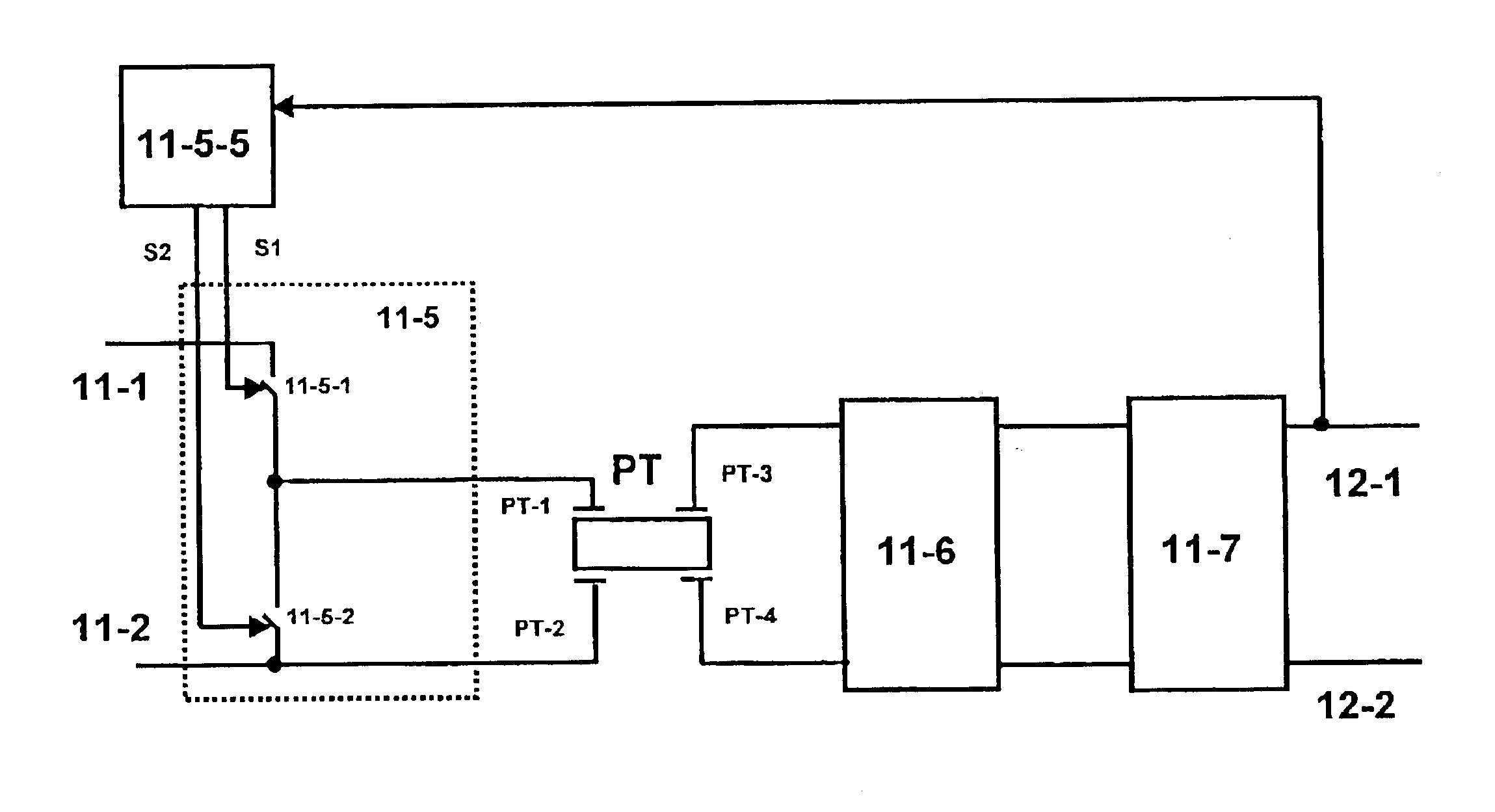
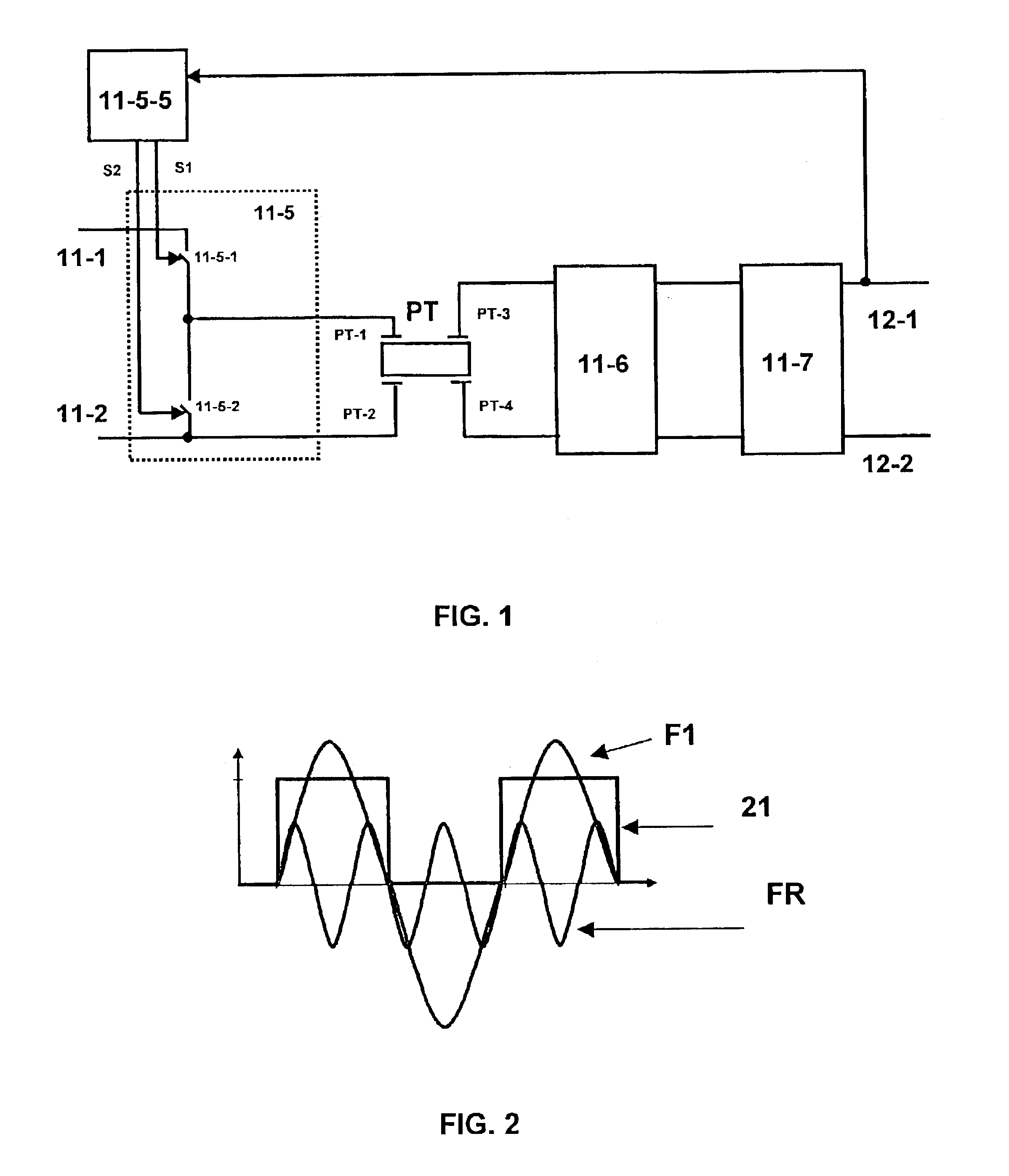
FIG. 1 represents a preferred embodiment of a switched power supply converter that has a piezoelectric transformer PT. The power supply converter performs the conversion of a first input voltage applied across some input terminals 11-1 and 11-2, to a second different voltage that is produced across some output terminals 12-1 and 12-2. The terminal 11-1, for example, is connected to the positive pole and the terminal 11-2 to ground, respectively.

A voltage source supplies the first input voltage. The voltage source can be a mains AC power supply distribution network, a DC voltage source, or others.

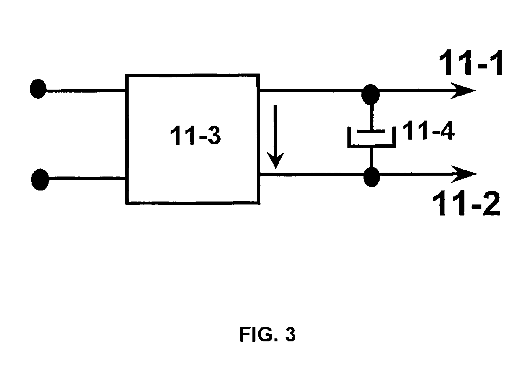
The switched power supply converter comprises, in a connection in cascade, a DC / AC converter block followed by a second rectifier 11-6 and thereafter a second filter 11-7, the output terminals of which coincide with the output terminals 12-1, 12-2 of the power supply converter.

The DC / AC converter block consists of a conversion topology such as one of the half-bridge type, for example, it bei...


PUM


Abstract

A piezoelectric transformer converts a first voltage, supplied from a voltage source, into a second, different, stabilized voltage by a DC / AC converter followed by a rectifier connected in cascade to a filter. The DC / AC converter block includes a driver block followed by the piezoelectric transformer, such that the driver block feeds the piezoelectric transformer with a pulse train (21) the frequency of which coincides with the switching frequency (F1) of switching elements included in the driver block. The switching frequency (F1) is less than a resonant frequency (FR) of the piezoelectric transformer; for example, the switching frequency is a sub-harmonic of the resonant frequency (FR).

Description

OBJECT OF THE INVENTIONThe present invention relates to a switched power supply converter which employs as transformer a piezoelectric transformer to perform a process of converting a voltage supplied from a power source into a different output voltage, suitable for being applied to a load.The galvanic isolation of the switched power supply converter is provided by the piezoelectric transformer, the operation of which is controlled by the switching of at least one switching element.The switched power supply converter is of special application, but not exclusively, in telecommunications systems since it offers a high performance with reduced size and weight.The piezoelectric transformer carries out the transformation of a is voltage applied across some primary terminals to a different voltage produced across some secondary terminals through the mechanical vibration of the piezoelectric transformer, using the piezoelectric effect.STATE OF THE ARTA switched power supply converter with ...

Claims


Application Information

Patent Timeline
Patent Type & Authority Patents(United States)
IPC IPC(8): H02M3/337H02M3/24
CPCH02M3/3376Y02B70/1433Y02B70/10
Inventor NAVAS SABATER, JOSE ANDRESRIVAS SAIZ, MERCEDESALOU CERVERA, PEDROPRIETO LOPEZ, ROBERTOUCEDA ANTOLIN, JAVIERCOBOS MARQUEZ, JOSE ANTONIO
Owner ALCATEL LUCENT SAS
Learn More