Miniature hydro-power generation system

a hydro-power generation system and miniature technology, applied in the field of electric power generation, can solve the problems of system portability, reduced electric power produced, and reduced capacity of hydro-electric power generation equipment, and achieve the effects of reducing losses, reducing costs, and efficient provision of sufficient power to opera

Inactive Publication Date: 2005-04-26
ACCESS BUSINESS GRP INT LLC
View PDF86 Cites 94 Cited by
  • Summary
  • Abstract
  • Description
  • Claims
  • Application Information

AI Technical Summary

Benefits of technology

[0012]The present invention discloses a miniature hydro-power generation system that overcomes problems associated with the prior art. The embodiments of the miniature hydro-power generation system are capable of efficiently providing sufficient power to operate electrical devices by rotating at high revolutions-per-minute (RPM), such as above 5000 RPM. High RPM operation is possible due to minimization of losses and maximizing translation of the kinetic energy in a flowing liquid to rotational energy to produce electric power.
[0014]The electrical generator may be a permanent magnet generator that is positioned within the cavity of the housing. The electrical generator includes a rotor coupled with the housing and a stator coupled with the centering rod. As the housing rotates, the rotor may be positioned in the housing to rotate around the stator and generate electric power. The rotor may produce a magnetic field that suspends the rotor around the stator in axial alignment. The housing may include bushings that surround the centering rod. Since the rotor is suspended around the stator, the housing is suspended around the centering rod. The bushings therefore surround the centering rod with little or no contact between the housing and the centering rod to reduce rotational friction and further improve efficiency as the housing rotates.
[0016]The housing may be positioned completely within an outer housing. The outer housing may include an interior surface and an outlet. The interior surface may include ducting to reduce liquid spray and therefore reduce fluid impedance when the stream of liquid is directed at the paddles. The ducting may include fingers and channels to reduce the liquid spray and also channel liquid out of the outer housing. The fingers and channels may be configured in a swirl pattern on the interior surface based on the dispersion pattern of liquid being flung from the rotating housing. Liquid may be continuously channeled out of the outer housing by the ducting so that the outer housing remains substantially dry. The inner housing and the nozzle may therefore operate without being submerged in the liquid to further reduce fluid impedance and improve efficient energy transfer.

Problems solved by technology

As a result, the amount of electric power produced diminishes as the size of the hydro-electric power generation equipment becomes smaller.
In the case of water treatment systems powered by electrical outlets, the system has limited portability and ceases to operate when there is an interruption in the electrical outlet power supply.
Water treatment systems operated from battery power sources contain only a finite supply of energy that is depleted through operation or storage of the water treatment system.
If a longer-term battery power source is desired, larger batteries are required that can add considerable weight and size to the water treatment system.
In addition, these water treatment systems require additional electrical circuits and components to operate from the two different power sources.
Where the automatic plumbing fixture is installed in an existing building, installation of a power distribution panel and / or an electric cable can be costly, time consuming and difficult.

Method used


Image

  • Miniature hydro-power generation system
  • Miniature hydro-power generation system
  • Miniature hydro-power generation system

Examples


Embodiment Construction

[0046]The exemplary embodiments of the invention are set forth below with reference to specific configurations, and those skilled in the art would recognize various changes and modifications could be made to the specific configurations while remaining within the scope of the claims. The presently preferred embodiments may be used with any system that requires a power supply and includes a water flow; however, the embodiments are designed for systems such as a water treatment system for residential or portable use, a plumbing fixtures, etc. Those skilled in the art would also recognize that the embodiments could be used with liquids other than water and use of the term “water” and “hydro” should not be construed as a limitation.

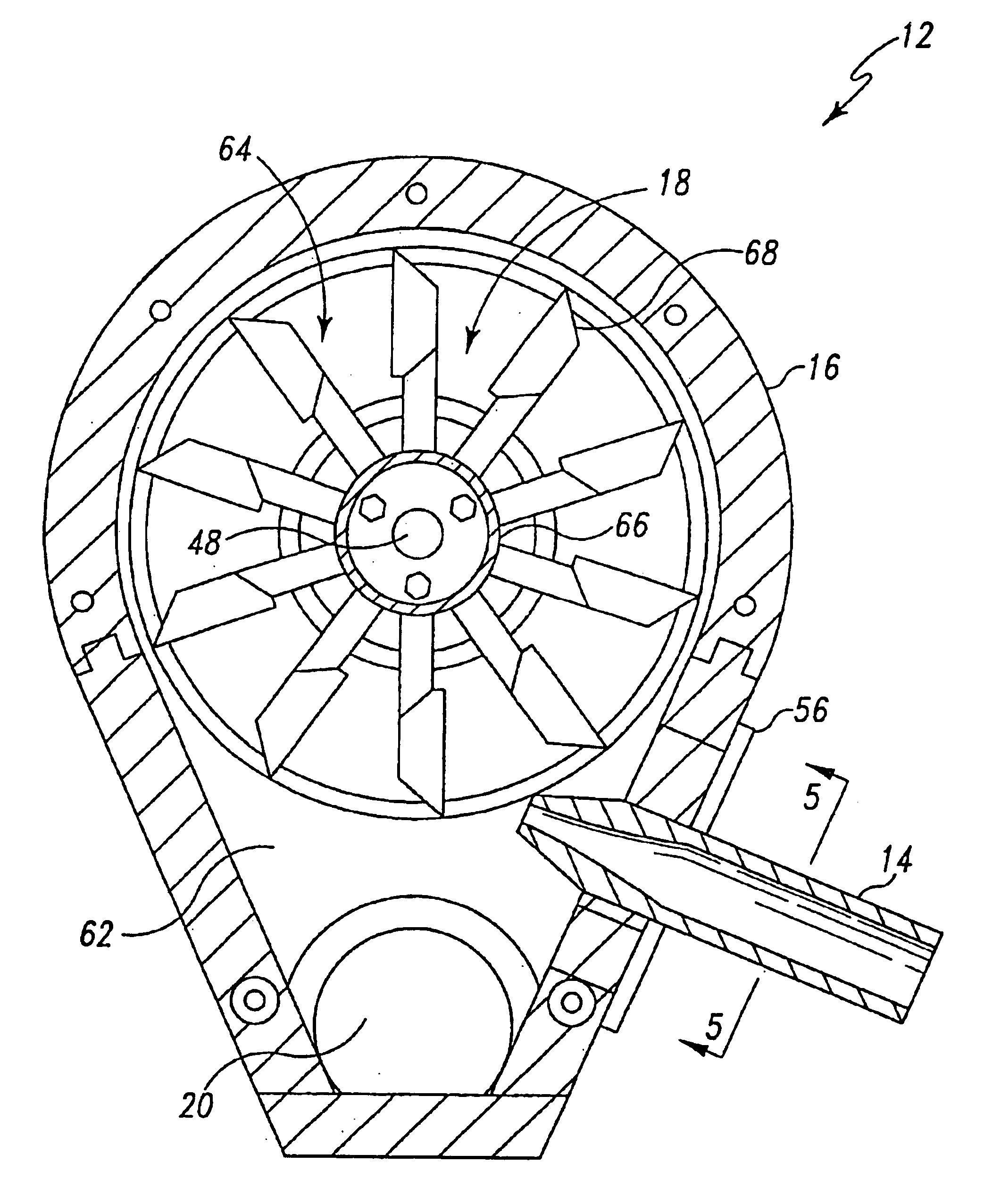
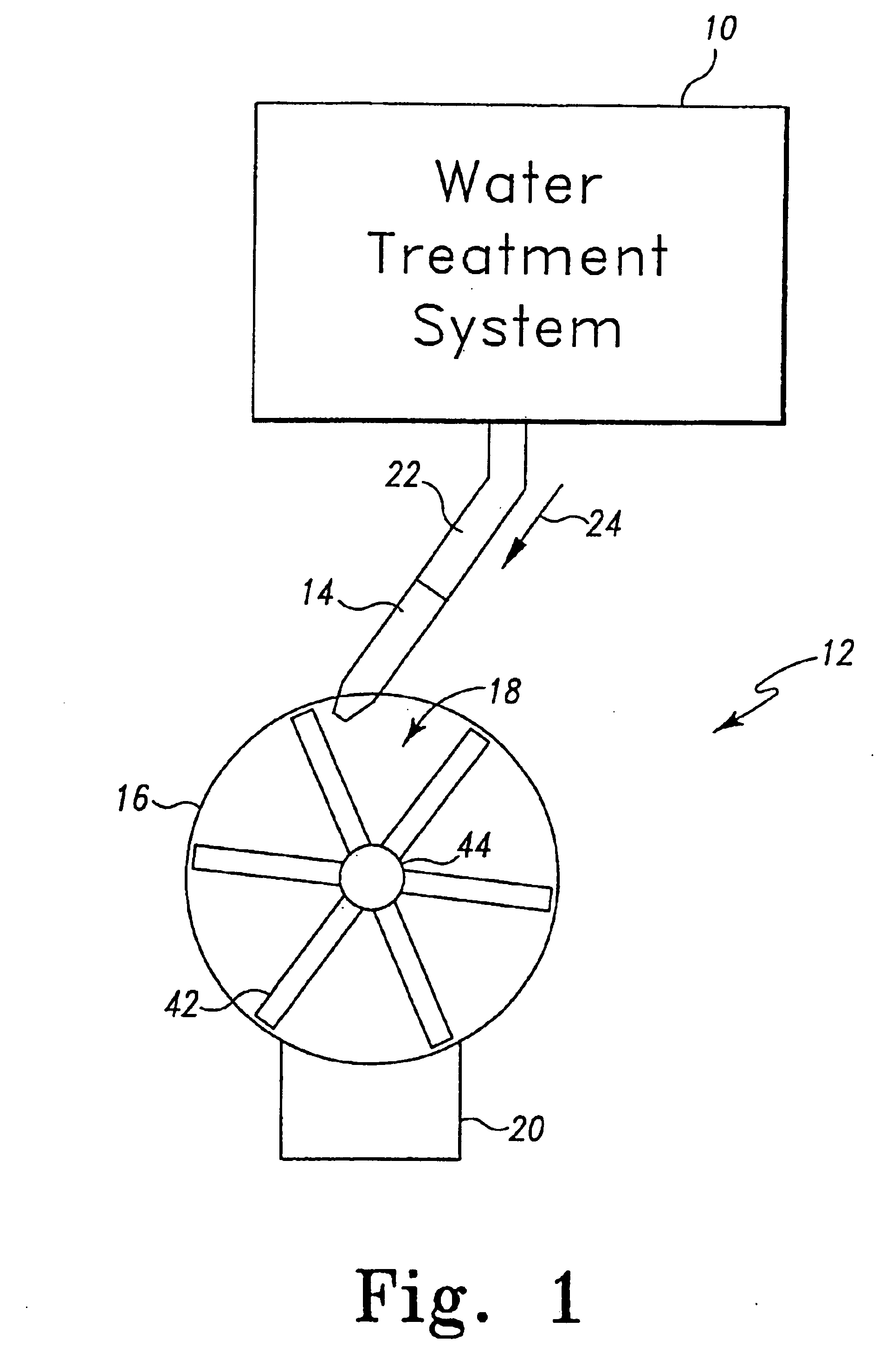
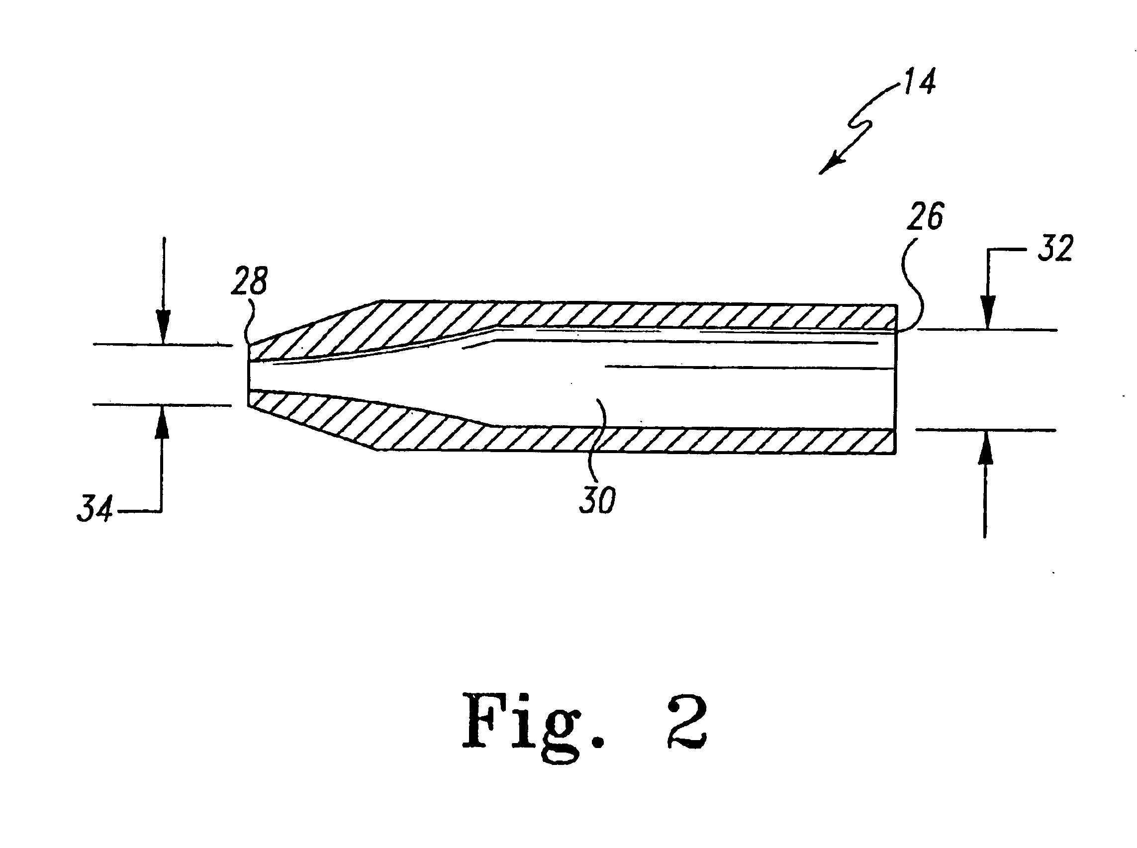
[0047]FIG. 1 is a side view of a water treatment system 10 connected with a preferred hydro-power generation system 12. In this embodiment, the hydro-power generation system 12 includes a nozzle 14, a housing 16, an impeller 18 and a housing outlet 20. The noz...


PUM

PropertyMeasurementUnit
diameteraaaaaaaaaa
diameteraaaaaaaaaa
flow trajectory angleaaaaaaaaaa

Abstract

A miniature hydro-power generation system may produce electric power from a flow of liquid. The miniature hydro-power generation system may include a housing that includes a plurality of paddles positioned to extend outwardly from an outer surface of the housing. The system may also include a nozzle and a centering rod extending through the housing. The housing may rotate around the centering rod when a stream of liquid from the nozzle is directed at the paddles. A generator that includes a rotor and a stator may be positioned within a cavity of the housing. The rotor may be coupled with the housing and the stator may be coupled with the centering rod. The rotor may rotate around the stator at high RPM to generate electric power when the housing rotates. The electric power may supply a load and / or may be stored in an energy storage device.

Description

[0001]This application claims the benefit under 35 U.S.C. §119(e) of Provisional U.S. patent application Ser. No. 60 / 417,337, filed on Oct. 9, 2002, which is herein incorporated by reference. In addition, this application is a continuation-in-part of U.S. patent application Ser. No. 09 / 680,345, filed on Oct. 5, 2000, now U.S. Pat. No. 6,798,080, issued Sep. 28, 2004, which claims the benefit of U.S. provisional patent application Ser. No. 60 / 157,760, filed on Oct. 5, 1999.FIELD OF THE INVENTION[0002]The present invention relates generally to electric power generation and, more particularly, to hydroelectric power generation with a miniature hydro-power generation system.BACKGROUND OF THE INVENTION[0003]Hydro-electric power generation in which kinetic energy is extracted from flowing pressurized water and used to rotate a generator to produce electric power is known. In addition, use of other pressurized fluids such as gas, steam, etc, to rotate a generator is known. With large hydro...

Claims


Application Information

Patent Timeline
Patent Type & Authority Patents(United States)
IPC IPC(8): F03B13/00H02K7/18C02F1/00C02F1/32E03C1/00F03B1/00F03B13/10H02P9/04
CPCC02F1/325C02F9/005E03C1/08F03B1/00F03B13/00H02K7/1823C02F1/008C02F1/001Y10T29/49009C02F1/283C02F1/32C02F2201/009C02F2201/3222C02F2201/326C02F2209/005C02F2209/006C02F2307/06E03C2201/40F05B2220/602F05B2240/2411Y02B10/50Y02E10/223Y02E10/28Y10T29/49229Y02A20/212Y02E10/20Y02P70/50Y02E10/30C02F9/20C02F2201/002C02F2201/32
Inventor BAARMAN, DAVID W.LAUTZENHEISER, TERRY L.
Owner ACCESS BUSINESS GRP INT LLC
Why Eureka
Try Eureka