Zero-voltage-switched, full-bridge, phase-shifted DC-DC converter with improved light/no-load operation

Inactive Publication Date: 2005-06-21
LA MARCHE MFG
View PDF9 Cites 83 Cited by
  • Summary
  • Abstract
  • Description
  • Claims
  • Application Information

AI Technical Summary

Benefits of technology

[0006]Accordingly, it is an object of the present invention to provide a full-bridge, zero-voltage-switched DC-DC converter which affords high operating efficiency at high and low output voltage loads, including at zero loading.
[0007]It is another object of the present invention to provide an arrangement for a DC switched mode power supply which maintains the stray and internal capacitances of the switching elements fully charged at high and low load conditions for improved power supply operating efficiency.
[0008]Yet another object of the present invention is to provide in a DC-DC converter incorporating plural switching devices arranged in a full bridge configuration essentially zero voltage across the switching devices during switching for reducing switching losses and electromagnetic interference and increasing operating efficiency.
[0009]The present invention contemplates an arrangement for converting a first DC input voltage t

Problems solved by technology

One disadvantage of the conventional ZVS-FB-PS converter is the dependence of the ZVS condition on the output load.
However, the incorporation of this large inductor gives rise to very high conduction loses when the load is high and also results in a decrease in the effective duty-cycle because of slower changes in the primary current polarity.
This increased induc

Method used


Image

  • Zero-voltage-switched, full-bridge, phase-shifted DC-DC converter with improved light/no-load operation
  • Zero-voltage-switched, full-bridge, phase-shifted DC-DC converter with improved light/no-load operation
  • Zero-voltage-switched, full-bridge, phase-shifted DC-DC converter with improved light/no-load operation

Examples


Embodiment Construction

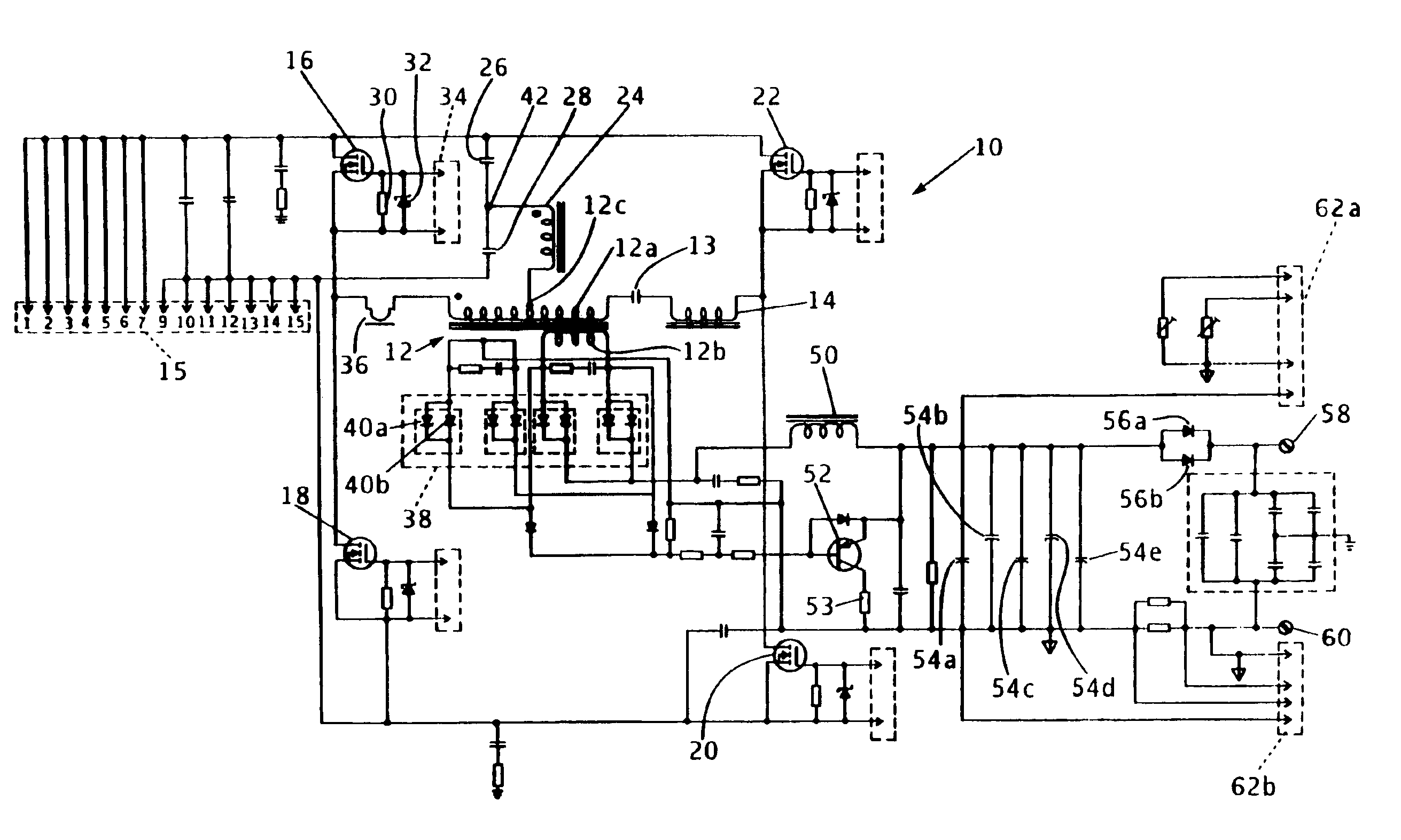
[0018]Referring to FIG. 1, there is shown a schematic diagram of a zero-voltage-switched, full-bridge, phase-shifted DC-DC converter 10 with light load or no-load operating conditions compensation in accordance with the principles of the present invention. The inventive DC-DC converter 10 is intended for use in a DC power supply where a DC input voltage is converted to a regulated DC output voltage. These types of DC power supplies are used in various applications such as in battery chargers, telecommunications systems, motor drives, etc.

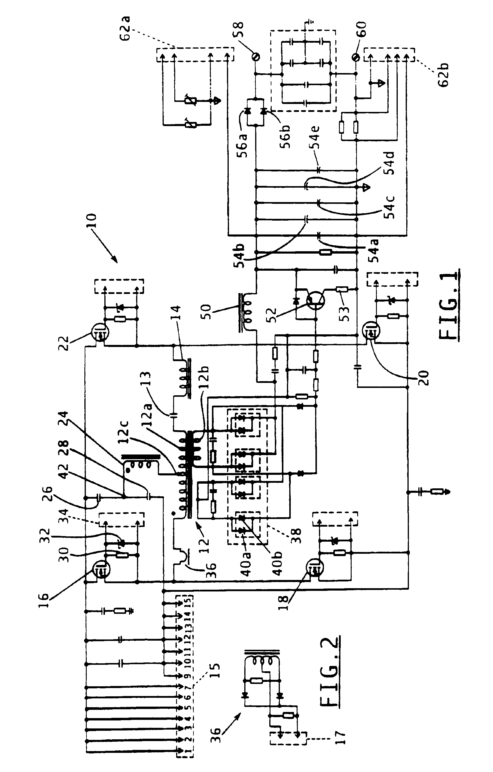
[0019]DC-DC converter 10 includes a power, or voltage, transformer 12 having a primary winding 12a and a secondary winding 12b. An input current is provided to the power transformer's primary winding 12a through the primary of a current transformer 36, which is shown in greater detail in the schematic diagram of FIG. 2. Connector 17 of the current transformer 36 secondary shown in FIG. 2 is used for connecting the current transformer to a feedback c...


PUM


Abstract

A zero-voltage-switched, full-bridge, phase-shifted DC-DC converter for use in a DC power supply or battery charger includes a power transformer, four switching transistors connected to form a full bridge, and a decoupling capacitor and resonant inductor connected in series to the primary winding of the power transformer. At high loads, i.e., high output voltages, the resonant inductor charges the stray and internal capacitance of the switching transistors. Under light loads or in a no-load condition, with the current through the resonant inductor insufficient to allow the inductor to recharge these capacitances, the combination of a second inductor connected at one end to the central tap of the power transformer's primary winding and at its second opposed end to the middle point of a capacitive voltage divider, permits the second inductor to store enough energy to effectively recharge the stray and internal capacitance of the switching transistors for improved operating efficiency.

Description

FIELD OF THE INVENTION[0001]This invention relates generally to DC power supplies or battery chargers and is particularly directed to an arrangement for increasing the operating efficiency of a zero-voltage-switched, full-bridge, phase-shifted DC-DC converter such as used in a DC power supply or a battery charger.BACKGROUND OF THE INVENTION[0002]Zero-voltage-switched (ZVS), full-bridge (FB), phase-shifted (PS) converters are commonly used for DC-DC conversion because of the several advantages that they offer over other approaches. These advantages include high efficiency, i.e., reduced duty cycle loss, due to zero-voltage-switching, or “soft” switching, a relatively small circulating energy, and constant frequency operation allowing for simple control of the converter. DC-DC converters of this type are typically incorporated in a wide range of DC power supplies having various applications such as in battery chargers.[0003]One disadvantage of the conventional ZVS-FB-PS converter is t...

Claims


Application Information

Patent Timeline
IPC IPC(8): H02M3/337H02M3/24
CPCH02M3/3376Y02B70/1433Y02B70/10
Inventor MIRSKIY, GREGORY
Owner LA MARCHE MFG
Why Eureka
Try Eureka