Heatsink apparatus and electronic device having the same

a heatsink and electronic device technology, applied in the field of heatsink apparatuses, can solve the problems of increasing insufficient capacity of cooling electronic components generating a large amount of heat, enhancing the performance of the heat receiver, and reducing the efficiency of the heatsink, so as to achieve excellent cooling performance, high heat-receiving performance, and high operation stability

Active Publication Date: 2009-04-02
PANASONIC INTELLECTUAL PROPERTY MANAGEMENT CO LTD
View PDF19 Cites 83 Cited by
  • Summary
  • Abstract
  • Description
  • Claims
  • Application Information

AI Technical Summary

Benefits of technology

[0016]As described above, the heatsink apparatus according to the present invention is provided with the slits in the internal wall from inside to outside on the surface surrounded by the external circumference of the opening of the inlet pipe. Thus, a heatsink apparatus can be provided having a high operation stability and an excellent cooling performance, the heatsink apparatus being capable of maintaining a high heat-receiving performance and of preventing a sharp temperature increase and dryout at an initial stage of heating.

Problems solved by technology

An increasingly important issue in view of normal operation of the electric components is how to maintain contact temperatures of the respective electronic components within a range of an operating temperature.
A conventional air cooling system that combines a heatsink and a fan, however, is increasingly insufficient in capacity for cooling electronic components generating a large amount of heat.
Due to the recent trend of increasing heat density, enhancing the performance of the heat receiver is particularly a big issue.
For instance, a heatsink apparatus capable of cooling a heat-generating body having an area of 100 mm2 and generating a heat of 100 W, might not be able to cool a heat-generating body having a reduced heat-generating area of 50 mm2, as a result of a thin line manufacturing process of electronic components, since the size reduction doubles the heat density, thus causing insufficiency in heat absorption capacity.
Thus, merely providing the pipeline inside the heat receiver does not generally achieve sufficient performance due to a limited heat-receiving area.
In addition, insufficient performance is expected to be further remarkable in accordance with future downsizing of heat-generating bodies.
The alternative conventional heatsink apparatus that uses the heat pipe, as shown in FIG. 30, can contain only a small amount of working fluid due to a limited inner capacity.
Although the total heat transport capacity can be increased to a certain level by increasing the number of heat pipes, the problem of heat density increase remains as described above.
Even the measure, however, has a limit in the number of practically functioning heat pipes in view of arrangement.
There is still a difficulty remaining in both achieving sufficient heat transport capacity and solving the high heat density issue.

Method used


Image

  • Heatsink apparatus and electronic device having the same
  • Heatsink apparatus and electronic device having the same
  • Heatsink apparatus and electronic device having the same

Examples


first embodiment

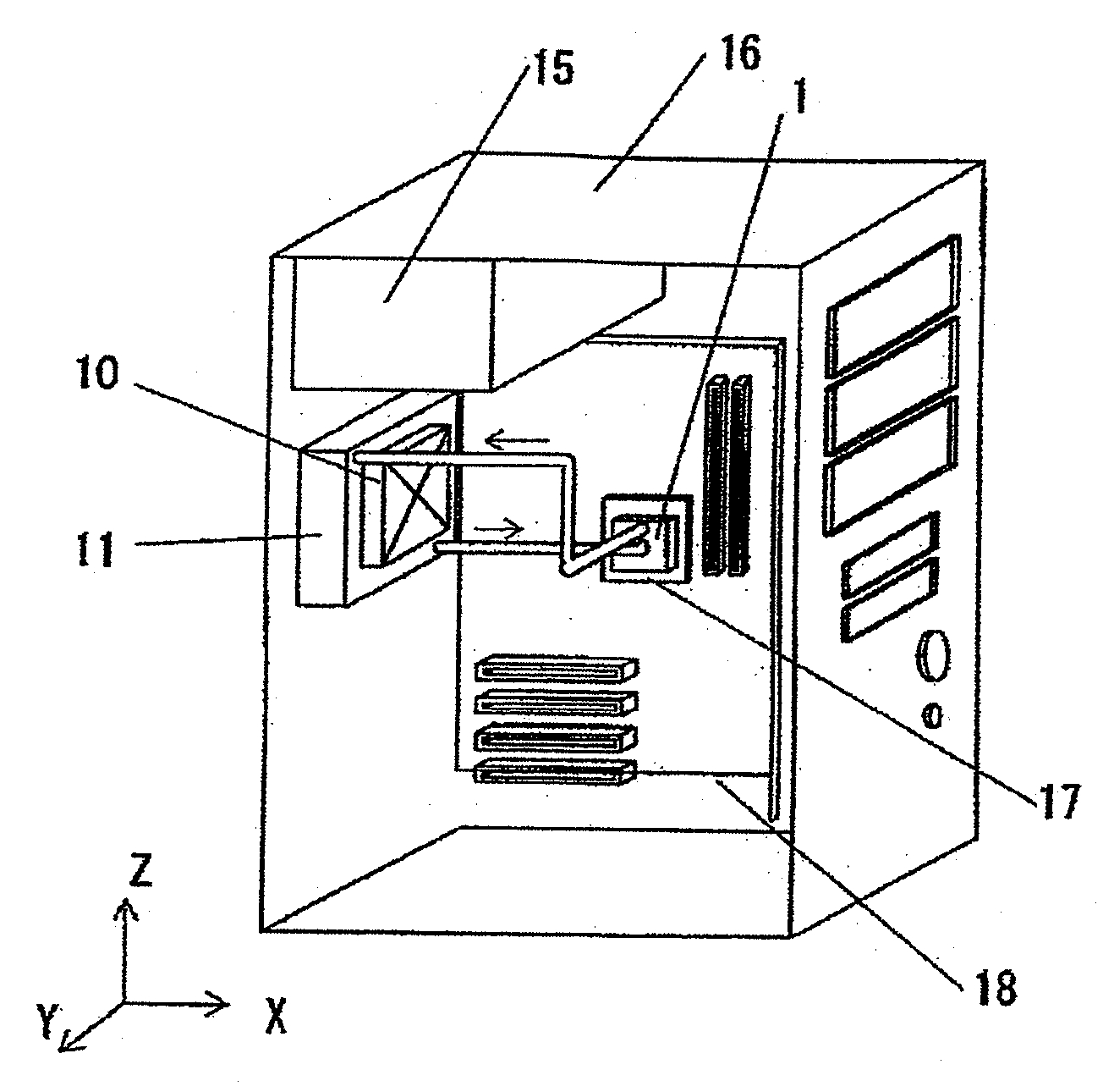
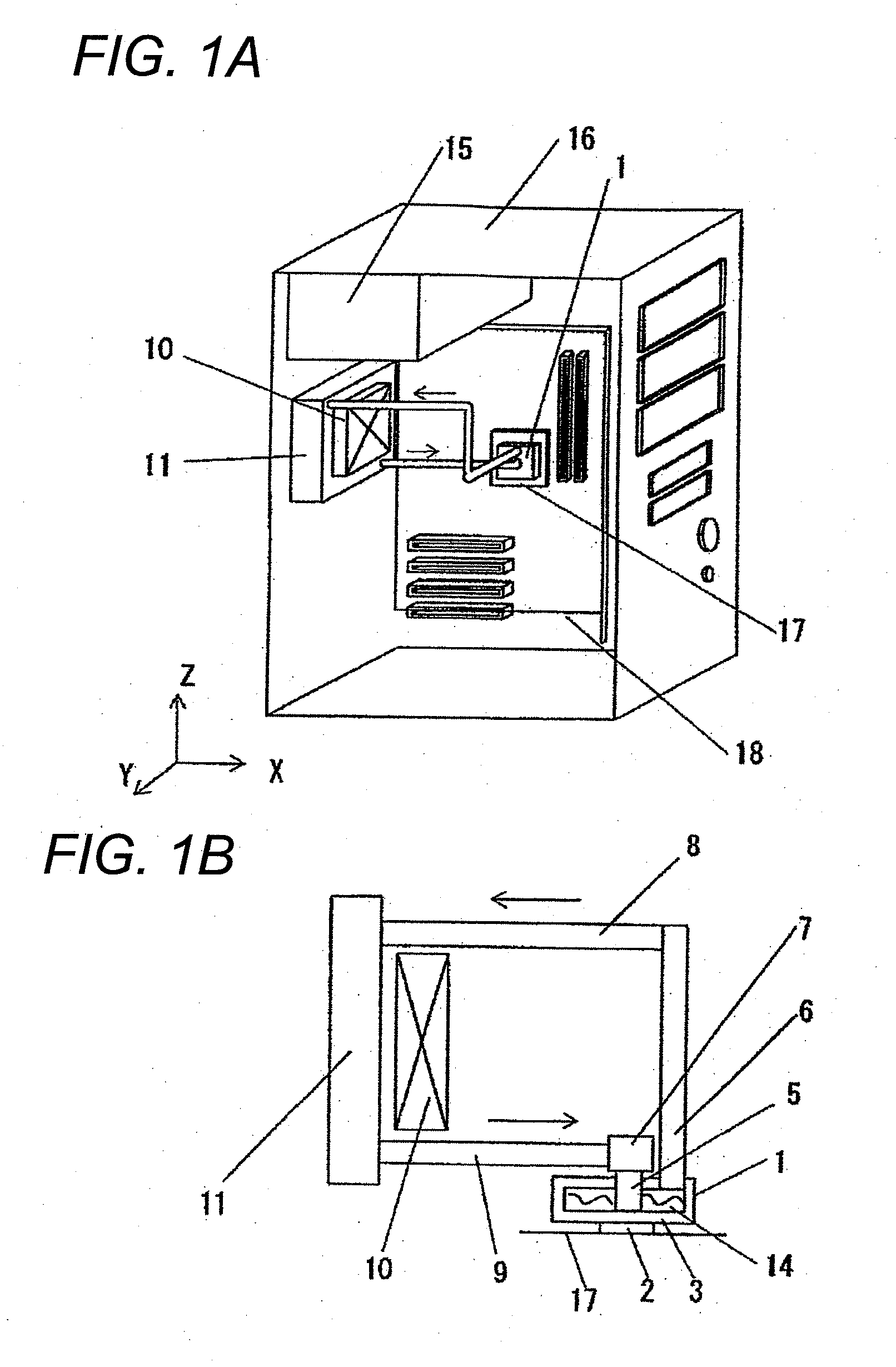
[0080]FIG. 1A is a perspective view when a heatsink apparatus according to a first embodiment of the present invention is provided in a personal computer (hereinafter referred to as a PC) unit; and FIG. 1B illustrates a structure of the heatsink apparatus of the present invention. As shown in FIG. 1A, PC unit 16 includes the heatsink apparatus according to the present invention, along with PC components, such as power source unit 15, motherboard 18, and the like. The heatsink apparatus includes box-shaped heat-receiving unit 1, which is connected to socket 17 of a heat-generating body, heat dissipater 11; and fan 10, which cools heat dissipater 11.

[0081]More specifically, the heatsink apparatus according to the present invention includes three main components and circulation components, as shown in FIG. 1B. The three main components are box-shaped heat-receiving unit 1, which includes heat-receiving plate 3; heat dissipater 11; and check valve 7, which determines a circulation direc...

second embodiment

[0103]In a second embodiment, the slits of the first embodiment are provided radially. For explanation purposes, identical reference numerals are provided to components identical to those in the first embodiment, and specific explanations thereof in the first embodiment are referred to.

[0104]A heatsink apparatus according to the second embodiment of the present invention is explained with reference to FIGS. 5A to 8D. FIG. 8A is a central vertical cross-sectional view of an alternative heat-receiving unit according to the second embodiment of the present invention; FIG. 8B is a cross-sectional perspective view of the heat-receiving unit of FIG. 8A; FIG. 8C is a horizontal cross-sectional view of the heat-receiving unit of FIG. 8A; and FIG. 8D is a cross-sectional detail view of portion A shown in FIG. 8A. As shown in FIG. 8A, slits 4, which are provided in heat-receiving plate 3 of heat-receiving unit 1 immediately above a heat-generating body, have a radial shape extending from a ce...

third embodiment

[0105]In a third embodiment, slits are not provided at a central portion of heat-receiving plate 3 contacting with heat-generating body 2. For explanation purposes, identical reference numerals are provided to components identical to those in the first and second embodiments, and specific explanations thereof in the first and second embodiments are referred to.

[0106]A case where slits 4 are provided in parallel is first explained with reference to FIGS. 9A to 9D. FIG. 9A is a central vertical cross-sectional view of heat-receiving unit 1 according to the third embodiment of the present invention; FIG. 9B is a cross-sectional perspective view of the heat-receiving unit of FIG. 9A; FIG. 9C is a horizontal cross-sectional view of the heat-receiving unit of FIG. 9A; and FIG. 9D is a cross-sectional detail view of portion A shown in FIG. 9A. As shown in FIG. 9A, slits 4, which are provided substantially in parallel in heat-receiving plate 3 of heat-receiving unit 1 immediately above a he...


PUM


Abstract

A heatsink apparatus performs cooling by circulating a working fluid and causing a phase change between a liquid phase and a gas phase. The heatsink apparatus is provided on an external wall with a heat-generating body. The heatsink apparatus includes a box-shaped heat-receiving unit transferring heat to a heat-receiving plate; an inlet pipe supplying the working fluid to the heat-receiving unit; an outlet pipe discharging vapors into which the working fluid supplied to the heat-receiving plate is evaporated by heat; and a heat dissipater provided at a location higher than the heat-receiving unit and dissipating heat of the vapor passing through the outlet pipe. Slits are provided to the heat-receiving plate on a surface surrounded by an external circumference of the inlet pipe toward outside of the heat-receiving plate.

Description

CROSS-REFERENCE TO RELATED APPLICATIONS[0001]The present application claims priority under 35 U.S.C. §119 of Japanese Application Nos. 2007-254040 and 2007-254044 filed on Sep. 28, 2007, the disclosure of which is expressly incorporated by reference herein in its entirety.BACKGROUND OF THE INVENTION[0002]1. Field of the Invention[0003]The present invention relates to heatsink apparatuses that cool semiconductors that produce heat, such as microprocessing units (hereinafter referred to as MPUs) used in personal computers and the like, and electronic components having heat-generating portions.[0004]2. Description of Related Art[0005]With higher integration of electronic components, such as semiconductors, and higher frequency of operation clocks, electronic devices have recently been generating an increasing amount of heat. An increasingly important issue in view of normal operation of the electric components is how to maintain contact temperatures of the respective electronic compone...

Claims


Application Information

Patent Timeline
Patent Type & Authority Applications(United States)
IPC IPC(8): F28D15/00H05K7/20
CPCF28D15/0266G06F1/20H01L23/427H01L2924/0002H01L2924/00
Inventor SATOU, KAORUKOUNO, HARUHIKO
Owner PANASONIC INTELLECTUAL PROPERTY MANAGEMENT CO LTD
Why Eureka
Try Eureka