This helps you quickly interpret patents by identifying the three key elements:
Problems solved by technology
Method used
Benefits of technology
Benefits of technology
The invention allows for a seamless viewing experience of a radio program by finding a receiving relay station even if the received radio waves deteriorate. This means that the program can be viewed without interruption even if it moves to another area.
Problems solved by technology
If a relay station sends a broadcast radio wave at the same frequency (SFN: Single Frequency Network), a program can be continuously viewed even if a movable body moves to other receiving area However, if a relay station sends a broadcast radio wave at different frequency (MFN: Multi Frequency Network), when a movable body moves to other receiving area, a program that has been viewed till then cannot be received.
While carrying out this channel search, there is an inconvenience that the program cannot be viewed.
Method used
Image
Click on the blue label to locate the original text in one second.
Reading with bidirectional positioning of images and text.
Examples
embodiment 1
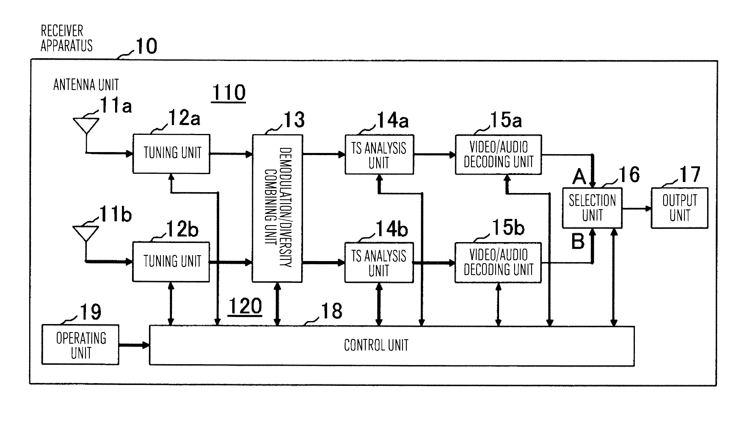
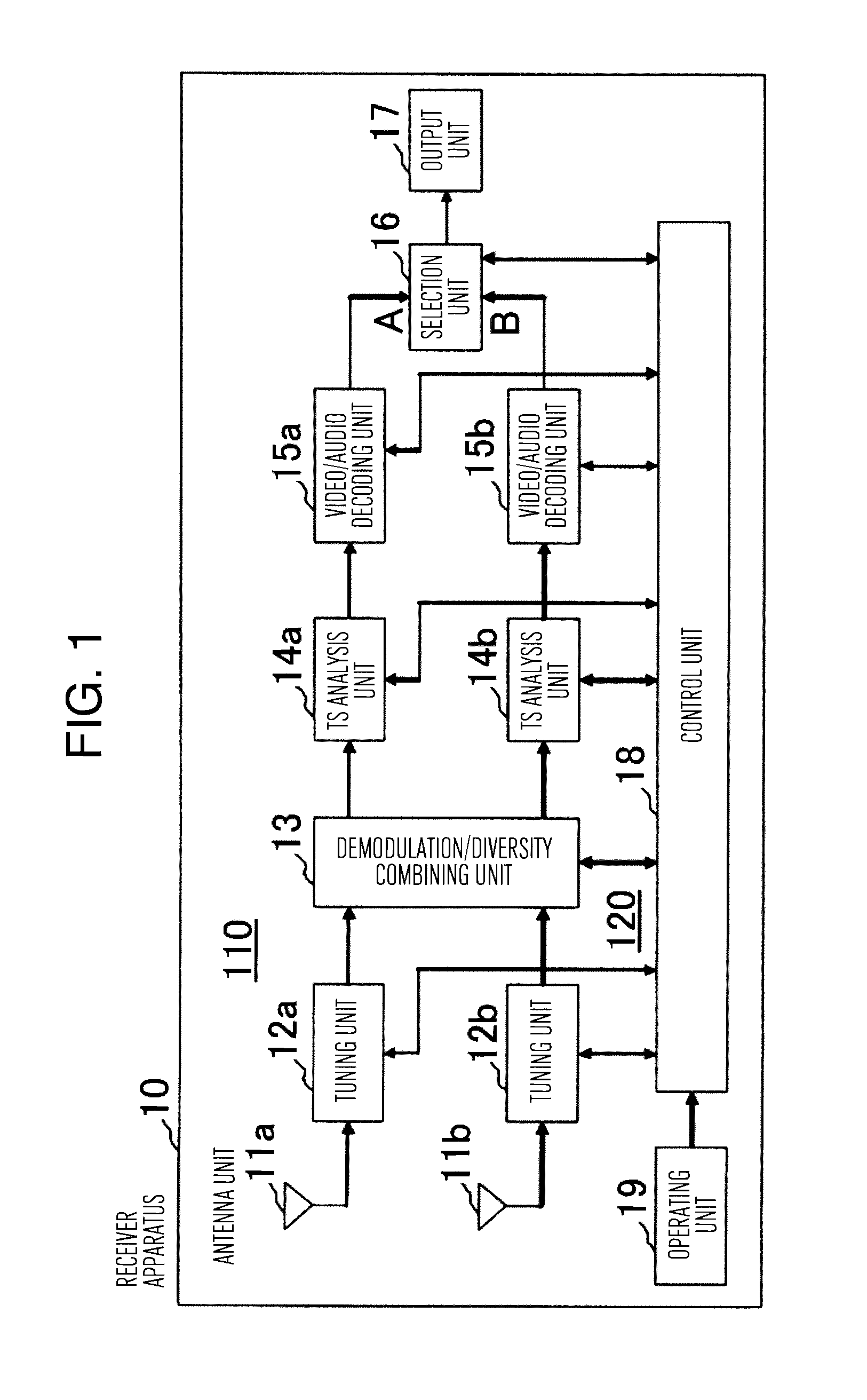
[0035]FIG. 1 is a block diagram showing the configuration of a receiver apparatus 10 in a first embodiment of the present invention.
[0036]In this view, a first receiving circuit unit 110 constitutes a first receiving system. The first receiving circuit unit 110 includes an antenna unit 11a, a toning unit 11b, a demodulation / diversity combining unit 13, a TS analysis unit 14a, and a video / audio decoding unit 15a. The antenna unit 11a receives broadcast radio waves, and supplies the same to the tuning unit 12a. The tuning unit 12a extracts, among the supplied broadcast radio waves, a channel specified by a control unit 18 to be described later and performs a frequency conversionprocessing on the extracted channel and supplies a desired channel signal to the demodulation / diversity combining unit 13.
[0037]Moreover, a second receiving circuit unit 120 constitutes a second receiving
[0038]system. The second receiving circuit unit 120 includes an antenna unit 11b, a tuning unit 11c, the de...
embodiment 2
[0073]FIG. 4 is a flow chart showing the operation of the control unit 18 in a second embodiment of the present invention.
[0074]In the second embodiment, the channel search using either one of the tuning units is regarded as one set, and this one set of channel search is periodically executed when the receiving state of the radio wave of a viewed program deteriorates (in the first embodiment, the tuning units 12a and 12b are alternately set as the tuning unit for search, respectively, and a total of two times of channel searches are regarded as one set).
[0075]In the flow chart of FIG, 4, first, in Step S401 the fact that the tuning unit 12a is used as the tuning unit for search is stored. The tuning unit 12a is just an example, and the tuning unit 12b may be used,
[0076]Next, in Steps S201 and 8202, as with the first embodiment, the diversity combining reception using the tuning units 12a and 12b is carried out, and the selection unit 16 selects the video / audio signals on the A side ...
embodiment 3
[0083]In the first embodiment of the present invention, when the receiving state of a radio wave in the tuning unit for reception is bad in interchanging the tuning units for reception and for search and executing the channel search, the reception of a viewed program might be interrupted during the channel search.
[0084]Similarly, in the second embodiment of the present invention, when the receiving state of a radio wave in a tuning unit assigned to the tuning unit for reception is bad in setting either one of the tuning units to the tuning unit for reception, the reception of a viewed program might be interrupted during the channel search.
[0085]FIG. 5 and FIG. 6 are flow charts showing a third embodiment for correcting the above-described problems.
[0086]FIG. 5 is the flow chart of the FIG 1 showing the operation of the control unit 18 in the first embodiment added by a processing of Step 501.
[0087]In this view, in Step S501, the control unit 18 causes the tuning unit for search to s...
PUM
Abstract
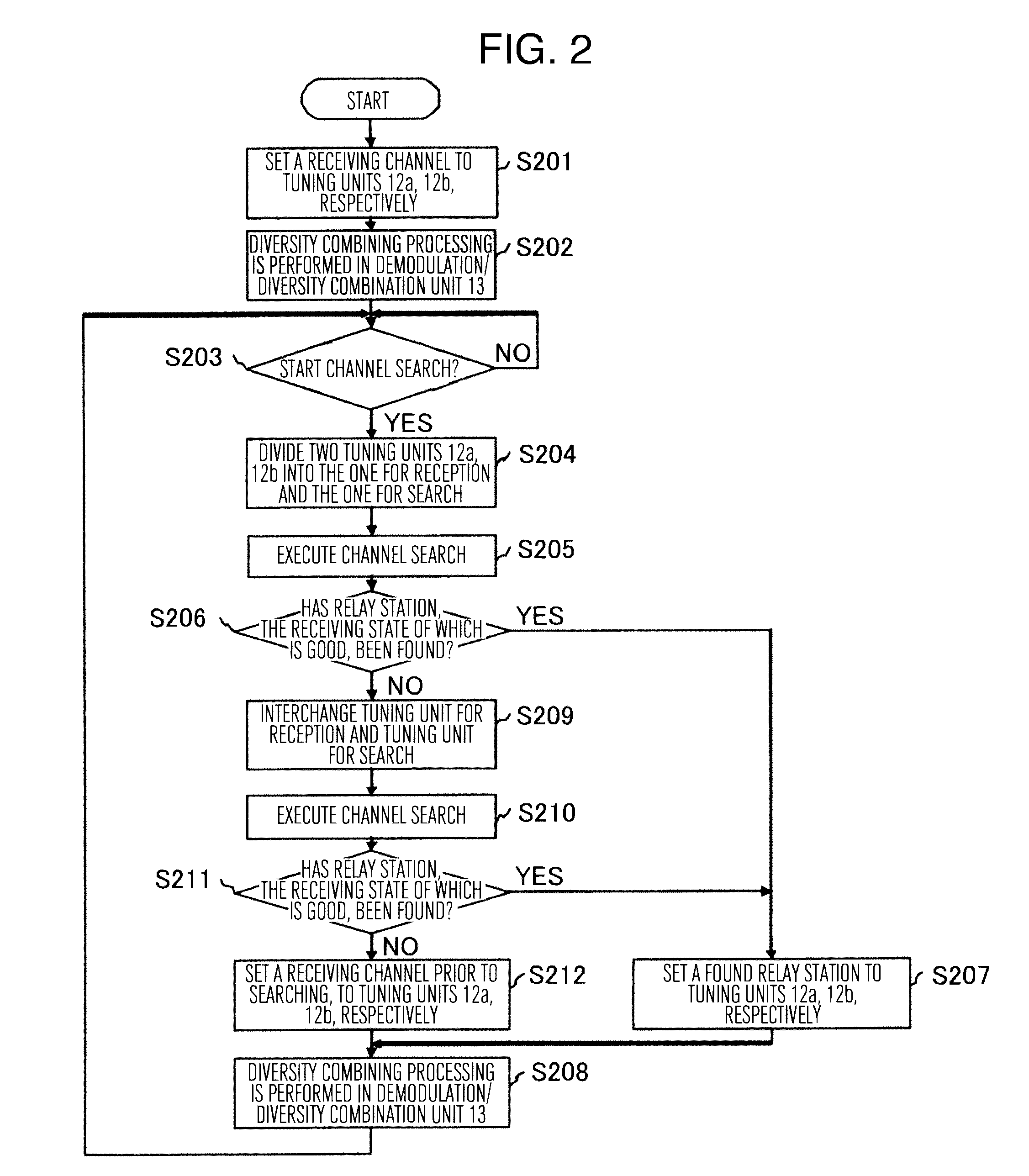
Receiver apparatus comprises: first and second receiving systems; a demodulation / diversity combining means for combining demodulated signals of first and second receiving systems; a selection means for selecting and outputting an output of either one of first and second receiving systems; and a control means for controlling the operations of the whole receiver apparatus. Control means causes to execute a first composite operation, either one of the receiving systems is caused to continue reception operation while the other receiving system is caused to perform channel search to search a channel satisfying a predetermined condition, further the selection means is caused to select output of the resulting receiving system for performing continuous reception operation. If no channel to be received is found, the control means controls to interchange the receiving system for performing continuous reception operation and the receiving system for performing channel search, and to perform a second composite operation.
Description
TECHNICAL FIELD[0001]The present invention relates to receiver apparatuses receiving communications and broadcasts, and in particular relates to a receiver apparatus mounted on a movable body and receiving terrestrial digital broadcasts while moving.BACKGROUND ART[0002]Usually, a broadcast station expands the receiving area of broadcasting by installing a relaystation at a plurality of locations within a broadcast area and sending broadcast radio waves from these relay stations. If a relaystation sends a broadcast radio wave at the same frequency (SFN: Single Frequency Network), a program can be continuously viewed even if a movable body moves to other receiving area However, if a relay station sends a broadcast radio wave at different frequency (MFN: Multi Frequency Network), when a movable body moves to other receiving area, a program that has been viewed till then cannot be received.[0003]For this reason, particularly in a broadcast receiver apparatus mounted on a movable body,...
Claims
Application Information
Patent Timeline
Application Date:The date an application was filed.
Publication Date:The date a patent or application was officially published.
First Publication Date:The earliest publication date of a patent with the same application number.
Issue Date:Publication date of the patent grant document.
PCT Entry Date:The Entry date of PCT National Phase.
Estimated Expiry Date:The statutory expiry date of a patent right according to the Patent Law, and it is the longest term of protection that the patent right can achieve without the termination of the patent right due to other reasons(Term extension factor has been taken into account ).
Invalid Date:Actual expiry date is based on effective date or publication date of legal transaction data of invalid patent.

