
Optical correction for high uniformity panel lights

a panel light and optical correction technology, applied in the field of optical correction of high uniformity panel lights, can solve the problems of significant loss of contrast ratio of the display, excessive reduction of gray levels at some pixel, and inability to achieve uniform light output, uniform colour, and the effect of improving uniformity

Inactive Publication Date: 2013-06-06
BARCO NV
View PDF7 Cites 6 Cited by
  • Summary
  • Abstract
  • Description
  • Claims
  • Application Information

AI Technical Summary

Benefits of technology

[0016]An object of the invention is to provide improved displays and especially panel light sources, e.g. backlights for displays and to corresponding methods. An advantage of the present invention is to provide good colour uniformity on one hand, and small thickness and low weight and cost on the other hand.
[0018]A display comprising addressable pixels and having a spatial light modulator for dynamically controlling a luminance of each pixel according to an input signal, the spatial light modulator having a non-uniform optical spatial characteristic, the display also having an optical filter and having a spatial pattern to alter the luminance and / or colour to compensate at least partially for the non-uniform spatial optical characteristic and having an electronic signal processing element arranged to apply some pre-compensation for the non-uniform optical spatial characteristic to the input signal.
[0019]The alteration of the luminance and / or colour is preferably to provide a more uniform light output across the display element as well as a more uniform colour.
[0020]An advantage of the optical filter is that the uniformity can be improved with reduced loss of any or all of contrast, grey levels, luminance and colour uniformity, compared to only electronic compensation. The materials used for the optical filter can be adsorbing, reflecting or emitting. Dichroic and bichromophoric materials are particularly preferred. The combination of dynamic and fixed compensation can enable some flexibility in the overall compensation, for tuning for different optimizations or for compensating for variations over time. The spatial light modulator can be any type of device including a reflective (e.g. DMD) a transmissive (e.g. LCD) or an emissive (e.g. LED) display or any combination thereof. In particular the display can be a fixed format display.
[0021]Another such additional feature is the pre-compensation being predominantly of higher spatial frequencies than spatial frequencies of the correcting spatial pattern.
[0022]Another such additional feature is the spatial light modulator comprising a transmissive or reflective device and the display comprising a light source.

Problems solved by technology

However, such electronic correction for non-uniformity introduces some important problems.
A first problem is a significant loss in contrast ratio of the display.
A second possible problem is that of excessive reduction in gray levels at some pixel positions on the display.
This problem can lead to a loss of visibility of some of the greys, in other words there can be “zero transitions” in the pixel behaviour.
It is no longer possible to map all 1024 gray scales on the dynamic range of the pixel and therefore some greyscale transitions (on pixel level) will no longer be visible.
Another issue is uniformity of colour across the display.
This is a particular issue for displays using a plurality of discrete light source such as LEDs as light sources for backlights as an alternative for fluorescent lamps.
However, this is only practical if the response time of the LCD is fast enough so that the sequencing can be done fast enough as to prevent annoying flicker on the display.
This spectrum is very badly matched to the typical transmission characteristics of the colour filters in colour LCDs, decreasing the efficiency and resulting in a very reduced gamut of colours that can be displayed.
One practical problem in realising a backlight with LEDs of different types of colours is that all colours have to be mixed very well first before the resulting mix can be coupled out of the backlight and sent to the display panel.
If the mixing is not done well in space, the colour of the resulting white mix will not be uniform over the active area of the display, and since the human eye is very sensitive to even small variations of the colour coordinates on a white field, this will be noticed soon by the display user.
The colour mixing problem cannot easily be solved by simple means when power LEDs are used, as is the case in most backlights, because they are relatively far apart from each other to make it possible to dissipate and sink the produced heat.
There are several disadvantages in this approach: the thickness and weight of the backlight almost doubles and the cost increases; unless the white balance of the light mix of the LEDs is perfectly equal for both LED arrays illuminating each separate light guide, a discontinuity in colour will be perceived in the middle of the screen.
It's also difficult to achieve luminance continuity in the middle of the screen for all viewing angles: if the current of both LED arrays is adjusted to achieve luminance uniformity for on-axis view (perpendicular to the screen), there is no guarantee that the luminance will be uniform in the middle at large viewing angles, because of structure is not symmetrical: one light guide is further away from the panel than the other, creating parallax and its emitted light must first travel through the other guide before it hits the diffuser.
Mura compromises the image quality of the finished display.
Deviations of that size spread over a large area can be difficult to detect by measuring.

Method used


Image

  • Optical correction for high uniformity panel lights
  • Optical correction for high uniformity panel lights
  • Optical correction for high uniformity panel lights

Examples


Embodiment Construction

[0050]The present invention will be described with respect to particular embodiments and with reference to certain drawings but the invention is not limited thereto but only by the claims. The drawings described are only schematic and are non-limiting. In the drawings, the size of some of the elements may be exaggerated and not drawn on scale for illustrative purposes. Where the term “comprising” is used in the present description and claims, it does not exclude other elements or steps.

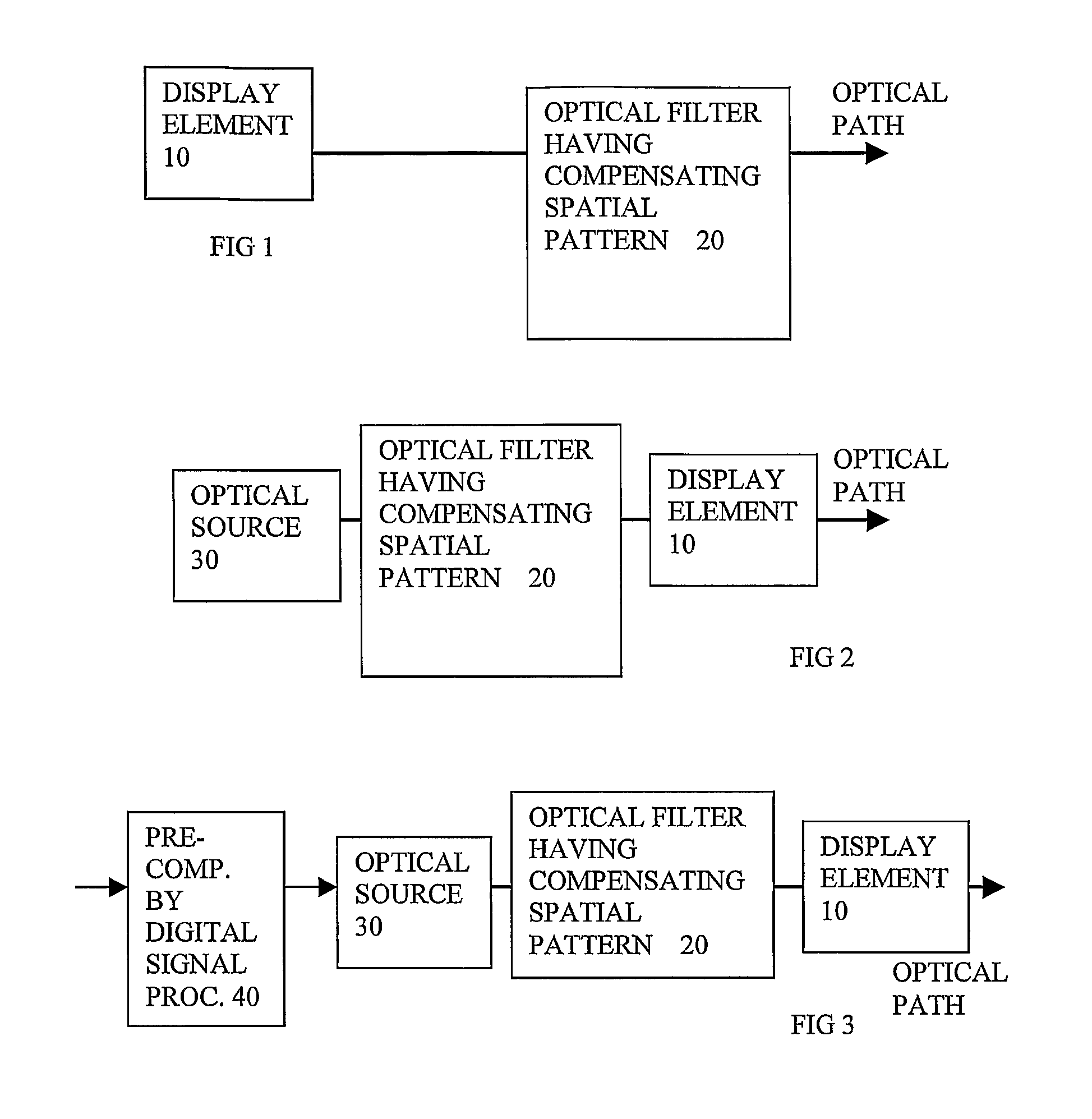
[0051]FIGS. 1-3, schematic views of embodiments of the invention:

[0052]FIG. 1 shows a schematic view of an embodiment of a display having a light source 30, coupled to a spatial light modulator 10 and an optical filter having a compensating spatial pattern 20. The spatial light modulator can be a reflective (e.g. DMD), a transmissive (e.g. LCD) or an emissive modulator (e.g. LED or OLED display). The spatial light modulator and optionally the light source as well, have a non uniform spatial optical ch...


PUM


Abstract

A display has a spatial light modulator for dynamically controlling a luminance of each pixel according to an input signal, the spatial light modulator having a non-uniform spatial characteristic, the display also having an optical filter having a spatial pattern to alter the luminance to compensate at least partially for the non-uniform spatial characteristic. An electronic signal processing element applies some pre ompensation predominantly of higher spatial frequencies for the non-uniform spatial characteristic. Such dynamic and optical compensation can enable tuning for different optimizations or for compensating for variations over time. A backlight has an optical source and an optical filter, the source having a color output which has a non-uniform spatial characteristic, and the optical filter having a spatial pattern to alter the color to compensate in part at least for the non-uniform spatial characteristic.

Description

FIELD OF THE INVENTION[0001]This invention relates to displays and to panel light sources, e.g. backlights for displays and to corresponding methods.DESCRIPTION OF THE RELATED ART[0002]There is a general requirement to provide panel light sources with a specific colour and preferably a uniform luminescence and colour over the surface area of the source. A traditional technique is to use light emitters of different colours, e.g. primary colours or colour filters, e.g. primary colour filters to set a particular colour, e.g. white of a certain colour temperature. Various techniques have been used to provide uniformity of luminescence, e.g. the use of diffusers.[0003]A number of techniques have been described in the past to achieve high uniformity display systems. One possibility is to use electronic pre-correction of the image signal. In the limit this can be done up to pixel level. It involves altering values in a frame buffer. This means that for each pixel the pixel data sent to tha...

Claims


Application Information

Patent Timeline
Patent Type & Authority Applications(United States)
IPC IPC(8): G09G3/06
CPCG02F1/133603G02F1/133606G02F1/133609G02F1/133611G02F2001/133607G09G3/3413G09G5/10G09G2320/0233G09G2320/0242G09G2320/0285G09G2320/0646G09G3/06G09G3/342G02F1/133607G09G3/3607G09G2320/0666
Inventor VERSTRAETE, GERRITKIMPE, TOM
Owner BARCO NV
Learn More