Irrigation catheter

a catheter and irrigation technology, applied in the field of catheters, can solve the problems of forming longer lesions, maintaining the temperature of any longer electrodes, and consuming a lot of tim

Inactive Publication Date: 2013-06-06
CATHRX LTD
View PDF3 Cites 4 Cited by
  • Summary
  • Abstract
  • Description
  • Claims
  • Application Information

AI Technical Summary

Benefits of technology

[0017]The fluid supply formation may be a recessed formation defined in the wall of the tubular member to be in fluid flow communication with the irrigation lumen of the tubular member. The connector may be mounted over the reces

Problems solved by technology

This is an extremely time-consuming process.
A difficulty with forming longer lesions

Method used


Image

  • Irrigation catheter
  • Irrigation catheter
  • Irrigation catheter

Examples


Embodiment Construction

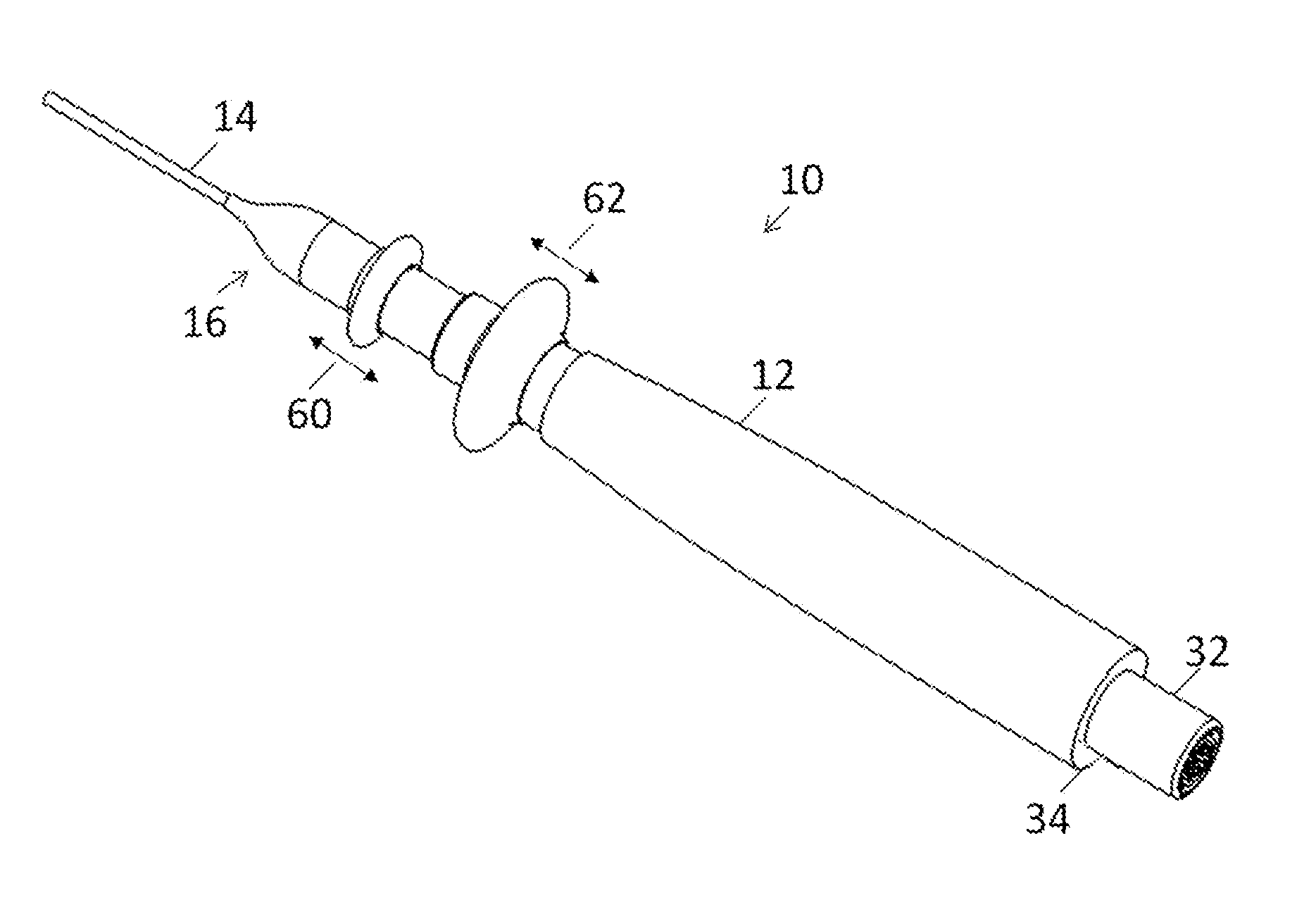
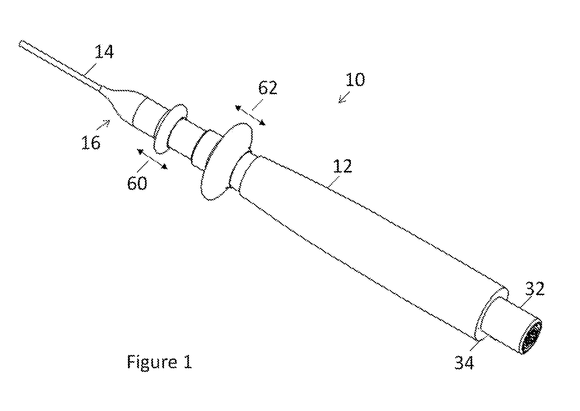
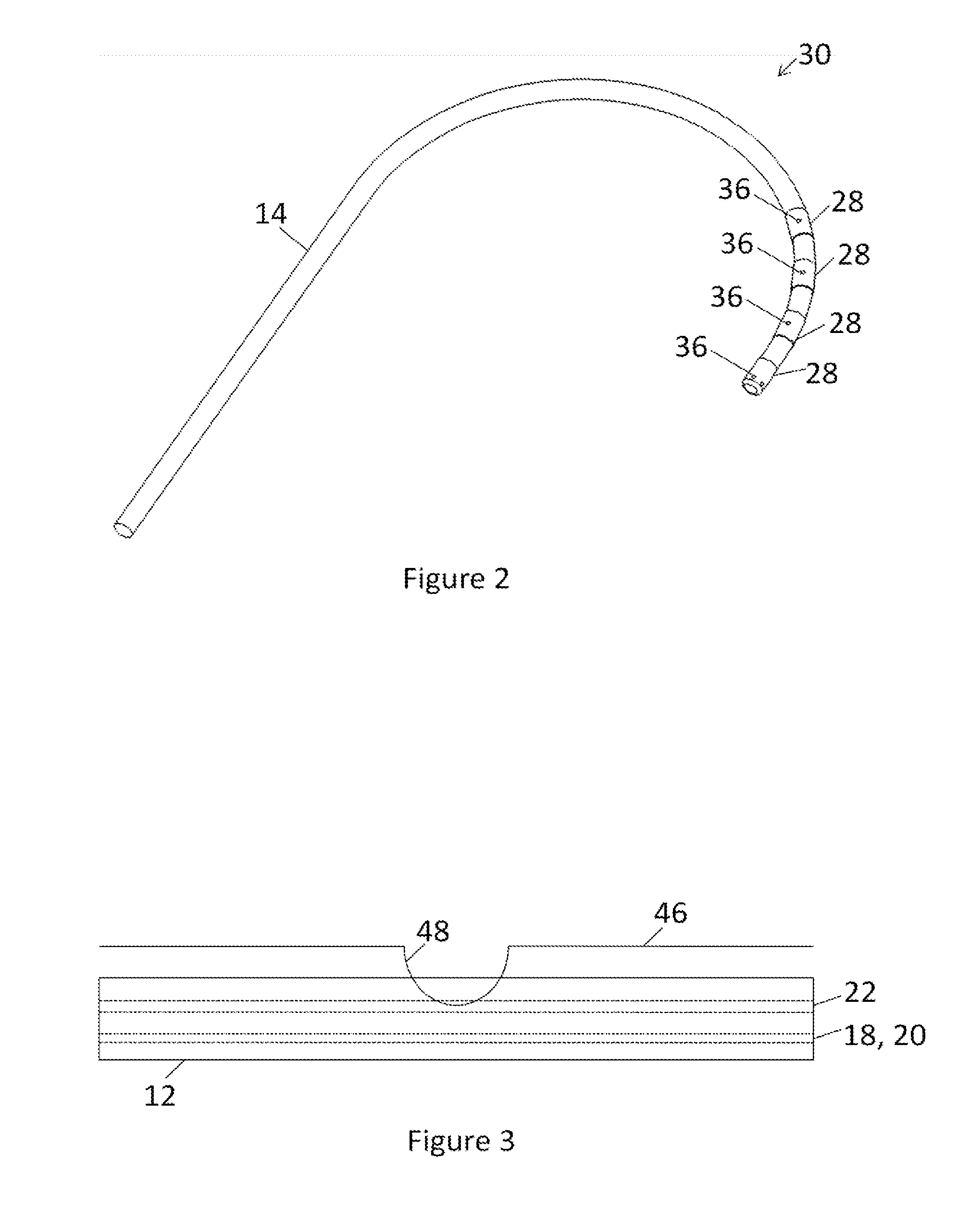
[0025]In FIG. 1, reference numeral 10 generally designates an irrigation catheter. The catheter 10 includes a handle 12. A catheter sheath 14 extends from a distal end 16 of the handle 12. The catheter sheath 14 defines a plurality of lumens 18, 20 and 22 (FIG. 5). The lumen 18 is a deflection stylet lumen for receiving a deflection stylet 24. The catheter handle includes a control knob for controlling the deflection by moving the control knob in the direction of arrow 62. The catheter handle may also include a size selector control knob for controlling the size of deflection curvature by moving the size selector knob in the direction of arrow 60. The lumen 20 is a conductor lumen and has a plurality of conductors (not shown) received therein, the conductors extending from electrodes 28 (FIG. 2) carried on a distal part 30 of the catheter sheath 14. The conductors extend through the handle 12 to an electrical connector 32 (FIG. 1) arranged at a proximal end 34 of the handle 12.

[0026...


PUM


Abstract

An irrigation catheter includes a handle, a catheter sheath with at least one ablation electrode proximal the distal end of the catheter sheath and a stylet for deflecting the distal end of the catheter sheath. The ablation electrode includes at least one irrigation opening in it. The irrigation catheter further includes a fluid-carrying formation formed on the catheter sheath under the ablation electrode. The fluid-carrying formation is in fluid communication with the irrigation lumen of the catheter sheath so that fluid is conveyed from the irrigation lumen to the irrigation opening.

Description

CROSS-REFERENCE TO RELATED APPLICATIONS[0001]This application is a national phase entry under 35 U.S.C. §371 of International Patent Application PCT / AU2011 / 001018, filed Aug. 12, 2011, designating the United States of America and published in English as International Patent Publication WO 2012 / 019229 A1 on Feb. 16, 2012, which claims the benefit under Article 8 of the Patent Cooperation Treaty and under 35 U.S.C. §119(e) to U.S. Provisional Patent Application Ser. No. 61 / 373,725, filed Aug. 13, 2010, the disclosure of each of which is hereby incorporated herein by this reference in its entirety.TECHNICAL FIELD[0002]This disclosure relates, generally, to a catheter and, more particularly, to an irrigation catheter.BACKGROUND[0003]Any discussion of the prior art throughout the specification should in no way be considered as an admission that such prior art is widely known or forms part of common general knowledge in the field.[0004]In the conduction of Maze-type procedures, an ablatio...

Claims


Application Information

Patent Timeline
IPC IPC(8): A61B18/14
CPCA61B18/1492A61B2218/002A61B2018/1467A61B2018/00577
Inventor RYAN, GARRETT
Owner CATHRX LTD
Why Eureka
Try Eureka