Rifle/shot gun recoil reduction system

Inactive Publication Date: 2013-06-13
VALIN NORMAN A
View PDF15 Cites 9 Cited by
  • Summary
  • Abstract
  • Description
  • Claims
  • Application Information

AI Technical Summary

Benefits of technology

The invention is a firearm that uses two pistons to provide equal pressure to the pistons and a recoil pad to absorb the recoil shock. The pistons have a pre-load of 250 kg and can be adjusted to change the pressure. The recoil pad reduces the recoil by 90%. This patent is about a new firearm system that reduces the recoil shock for the shooter while maintaining the effectiveness of the firearm.

Problems solved by technology

The shooter, and in particular the user of long guns, is often subjected to considerable impulsive forces in the rifle stock support zone or butt stock end plate.

Method used


Image

  • Rifle/shot gun recoil reduction system
  • Rifle/shot gun recoil reduction system
  • Rifle/shot gun recoil reduction system

Examples


Embodiment Construction

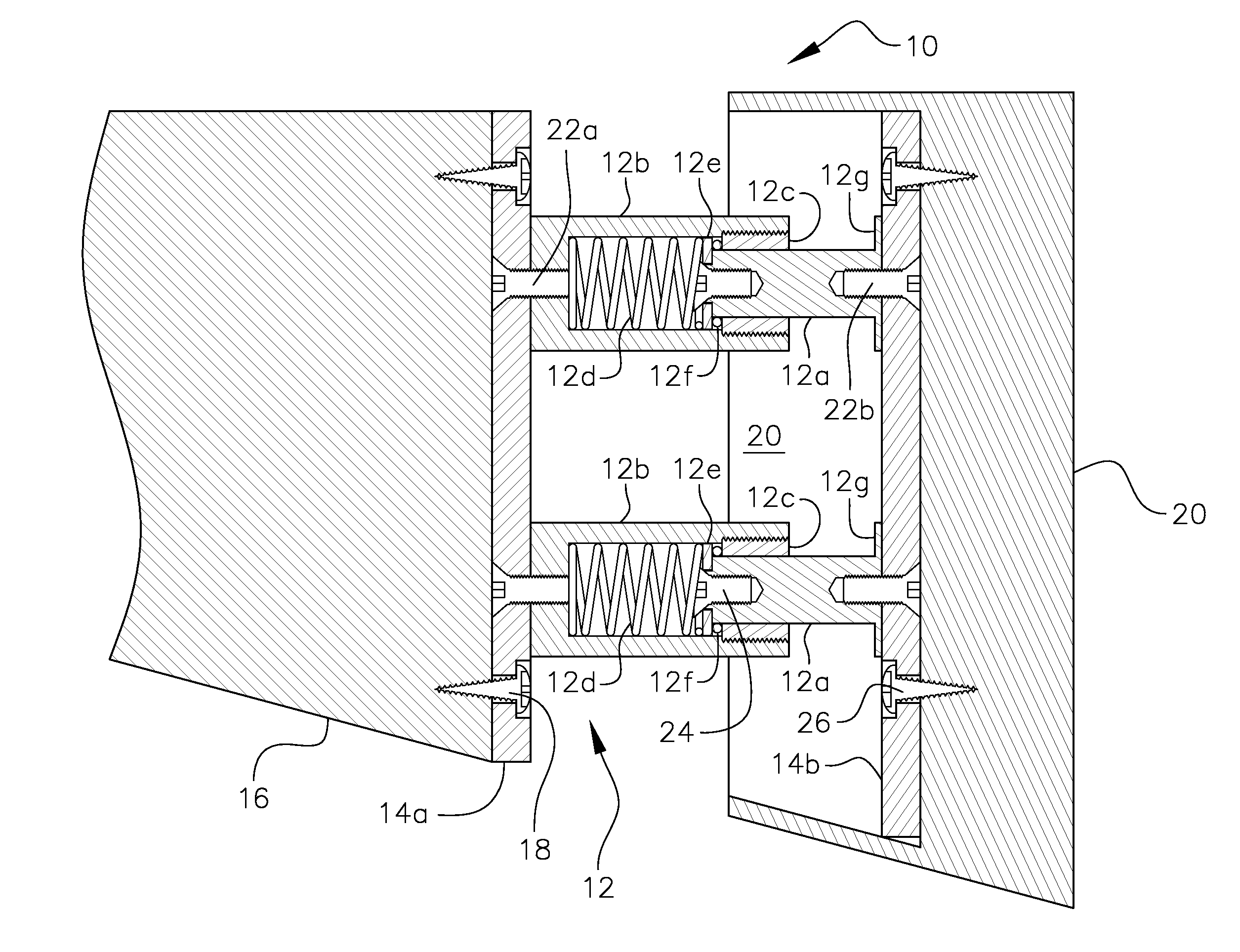
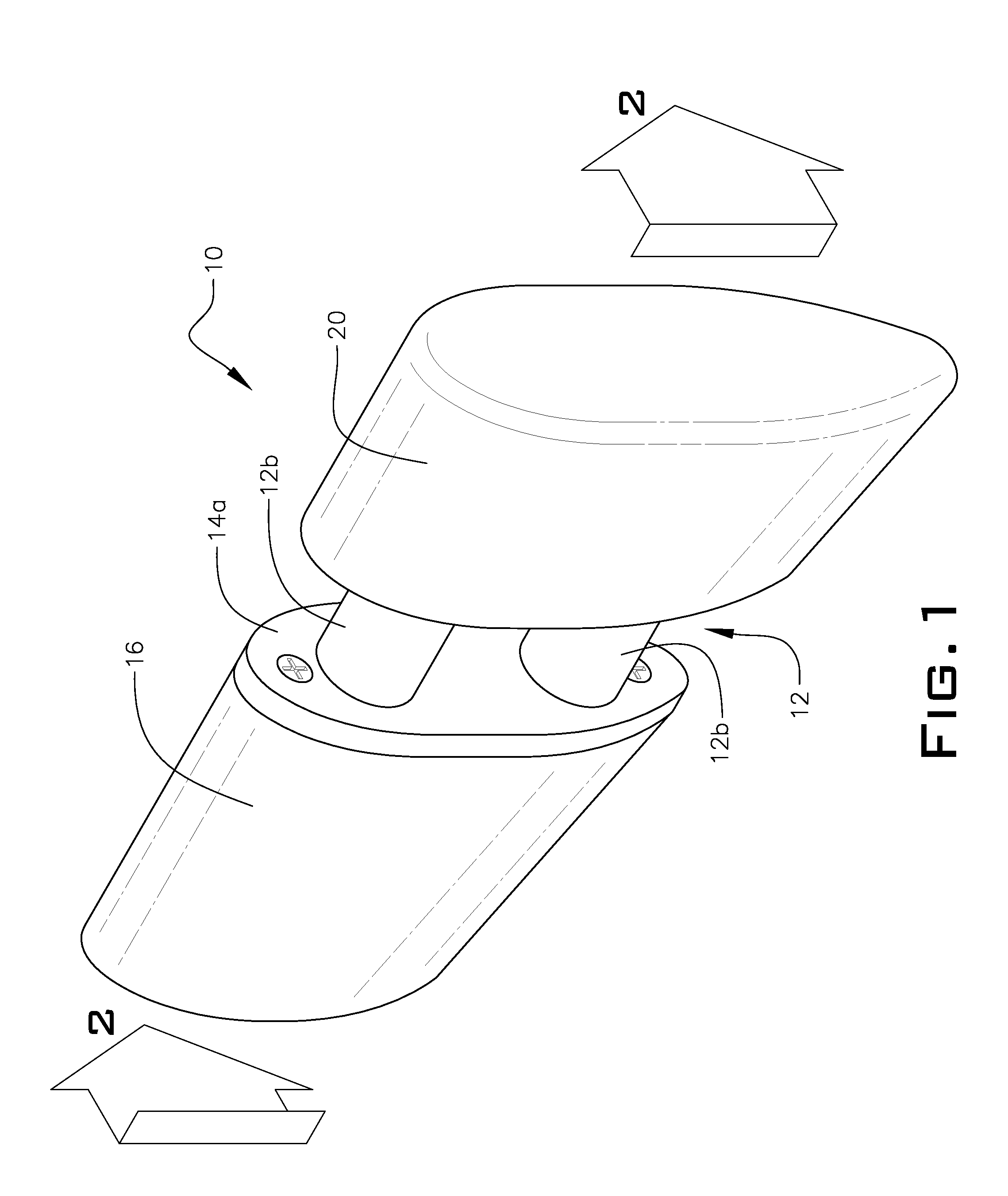
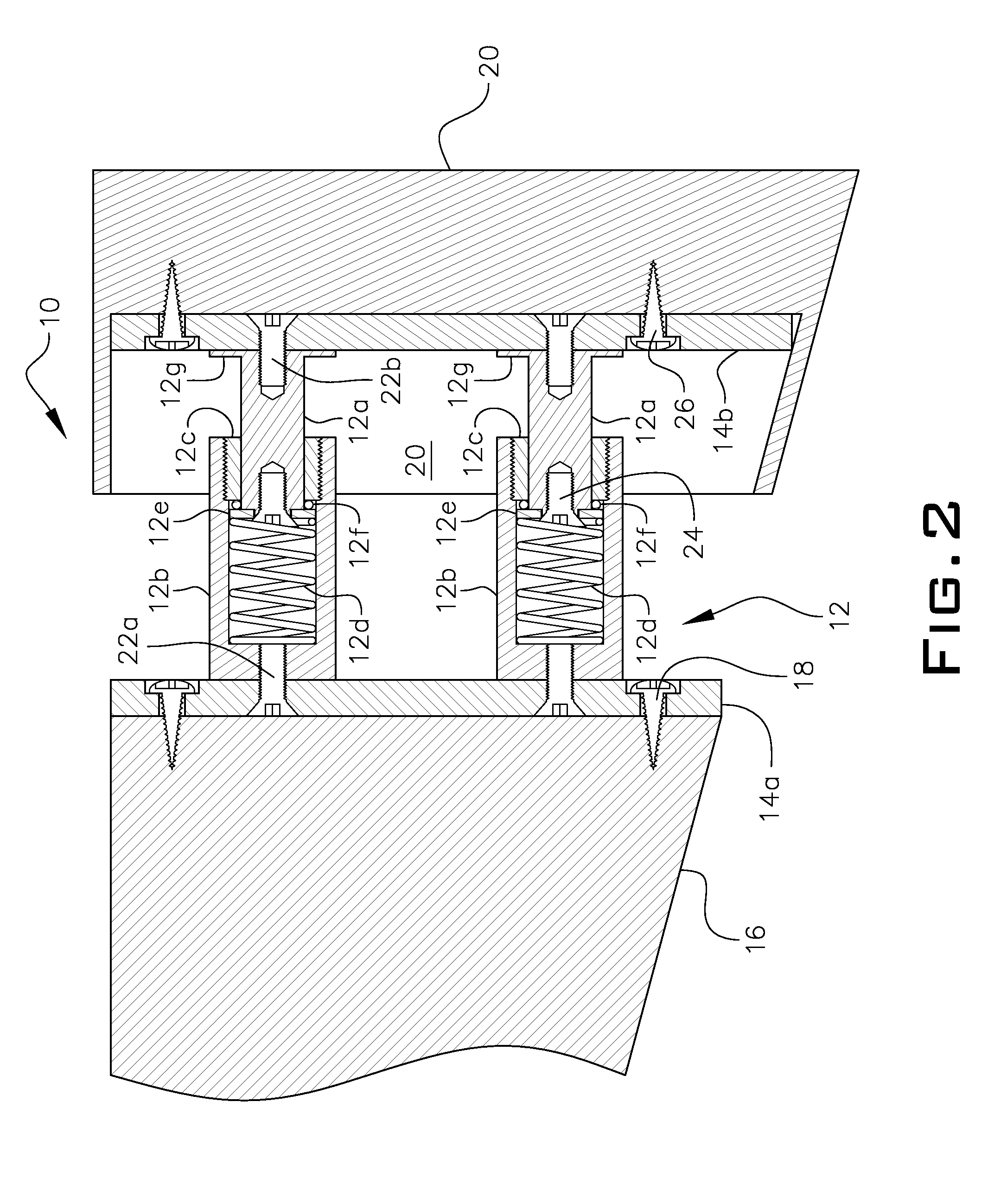
[0011]Referring now to the drawings, FIGS. 1 and 2 disclose a typical example of the present invention, which is a rifle recoil reduction system, depicted generally as 10.

[0012]The rifle recoil reduction system 10 comprises recoil damping means 12 for reducing a recoil impact of a rifle. The damping means 12 is mounted between two spaced-apart plates 14a,14b, wherein one of the plates 14a is configured to be attached to an outside surface of a butt end of a rifle stock 16. The attachment can be done in a number of ways known on the art but the preferred method is simply to use a couple of fasteners 18, like screws. As an example, FIG. 2 depicts fasteners 18 as being inserted into a counter-bore 3 / 32 inch deep×⅜ inch diameter using pan head 8×¾ inch long screws. Damping means 12 are typically fastened to each end plate 14a,14b, as shown in FIG. 2 by way of example.

[0013]The invention further comprises recoil padding means 20 for providing additional recoil impact absorption mounted t...


PUM


Abstract

A rifle recoil reduction system is presented for reducing a recoil impact of a rifle. The system includes two parallel spaced-apart spring operated piston assemblies mounted between two spaced-apart plates, separated in part to work simultaneously together to provide an equal amount of pressure to the pistons. The pistons preferably have a pre-load of about 250 kg (550 pounds), and can be changed to increase or decrease the pre-load. A recoil pad is included to provide additional relief to the shooter.

Description

FIELD OF THE INVENTION[0001]The invention relates to a recoil reduction system for rifles and shot guns, especially those used for hunting and sports activities.BACKGROUND OF THE INVENTION[0002]The recoil is a characteristic common to all firearm types, which leads to particularly significant effects in the case of longer guns. This phenomenon, a characteristic application of the action / reaction principle, indicates the impulse that causes the gun to move back due to the impulse that the gun imparts to the bullet when firing it. The shooter, and in particular the user of long guns, is often subjected to considerable impulsive forces in the rifle stock support zone or butt stock end plate. The discharge (firing) of a shoulder held firearm can generate forces of 300 kg (660 pounds) on up, which is impacted onto the shooter's shoulder. This happens through the end of the butt stock.[0003]The object of the present invention is to provide a retro-fit or original equipment manufactured re...

Claims


Application Information

Patent Timeline
IPC IPC(8): F41C23/08
CPCF41C23/08
Inventor VALIN, NORMAN A.
Owner VALIN NORMAN A
Why Eureka
Try Eureka