Inductively interrogated passive sensor apparatus

a passive sensor and inductive interrogation technology, applied in the direction of magnetic sensor geometrical arrangement, instruments, material magnetic variables, etc., can solve the problems of undesirable structure breaching, inability to use active electrical components in certain environments, and difficulty in achieving the effect of reducing the number of active electrical components

Active Publication Date: 2013-06-13
FMC TECH INC
View PDF17 Cites 25 Cited by
  • Summary
  • Abstract
  • Description
  • Claims
  • Application Information

AI Technical Summary

Benefits of technology

[0018]Another advantage of the present invention is that, since the second transducer and the sensor are non-powered devices and the active electrical components are located outside the barrier, the sensor apparatus of the present invention is particularly suitable for use in high pressure, high temperature and explosive environments.
[0019]Furthermore, since the sensor apparatus of the present invention effectively nulls out the eddy current-generated magnetic field at the receiver coil, the sensor apparatus is particularly effective for use in sensing conditions inside a conductive barrier. Moreover, this feature allows the sensor apparatus to work even when the transmitter coils are positioned near or against the conductive barrier, such as when the first transducer is mounted directly on the outer surface of the conductive barrier.

Problems solved by technology

However, breaching the structure for this purpose is undesirable, especially in structures containing high pressure fluids, such as oil pipelines.
However, the use of active electrical components in certain environments is problematic.
For example, with the exception of certain silicon carbide electronics, which are usable at temperatures of up to around 250° C. but are not available for most applications, even the highest rated Mil-Spec electrical components typically begin to fail at around 125° C. In this regard, even the high temperature solders which are used in such components usually begin to melt at about 220° C. Consequently, in certain structures, such as subsea oil pipelines, where temperatures can reach 180° C. to 320° C. or higher, the use of active electrical components is not practical.
Furthermore, although inductively interrogated passive sensor systems exist in the prior art, to the inventors' knowledge these systems do not work when the passive sensor is positioned entirely within or against a conductive barrier.
However, this system will not work when the antenna and the entire passive sensor are positioned on opposite sides of a conductive barrier.
In addition, even when positioned outside the conductive barrier, the system will not work when the inductor is positioned against the barrier due to the large eddy currents which the magnetic field generates in the barrier.

Method used


Image

  • Inductively interrogated passive sensor apparatus
  • Inductively interrogated passive sensor apparatus
  • Inductively interrogated passive sensor apparatus

Examples


Embodiment Construction

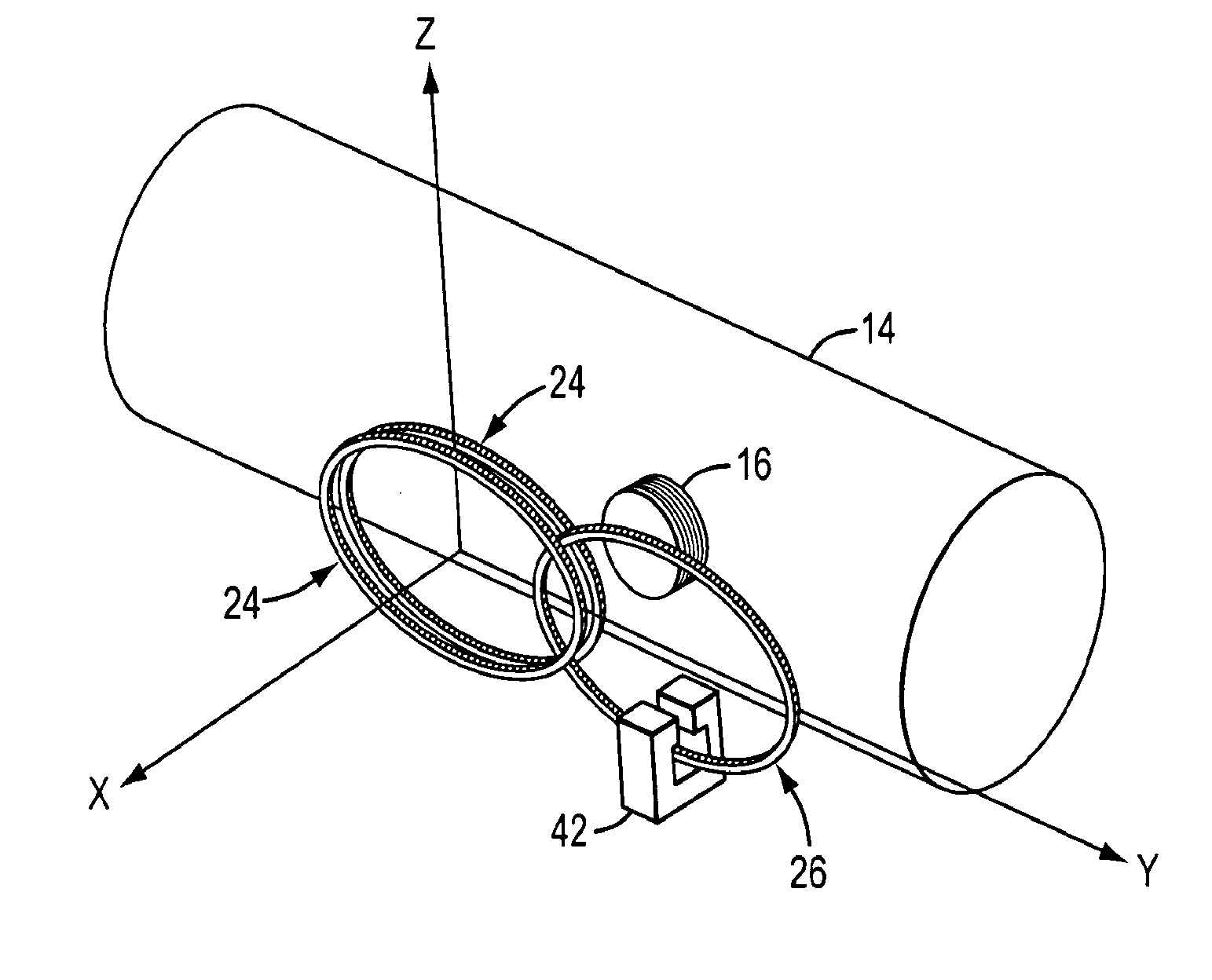
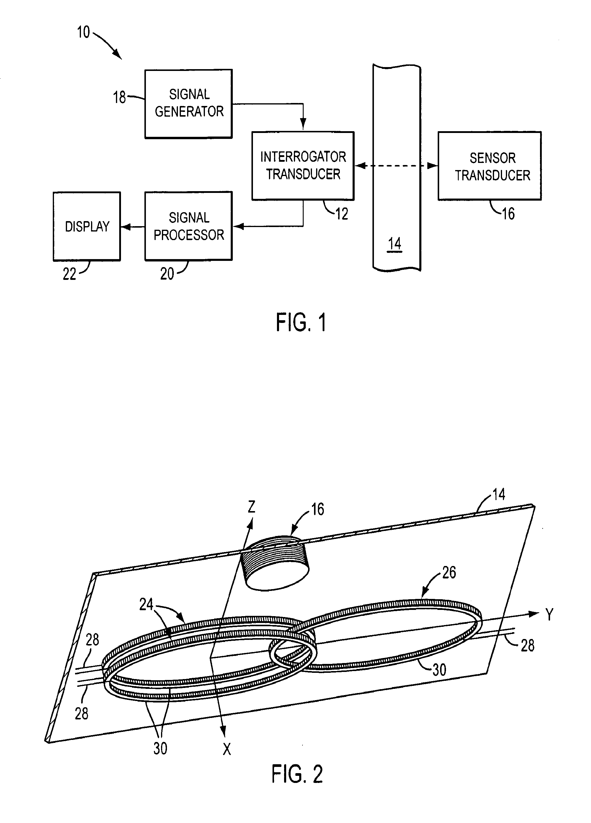
[0034]A block diagram of an illustrative embodiment of the sensor apparatus of the present invention is shown in FIG. 1. The sensor apparatus of this embodiment, which is indicated generally by reference number 10, comprises a magnetic interrogator transducer 12 which in use is positioned on one side of a barrier 14, and a magnetic sensor transducer 16 which in use is positioned on the opposite side of the barrier and is magnetically coupled to the interrogator transducer. In this embodiment of the invention, a preferably very low frequency (VLF) AC signal from a signal generator 18 is applied to the interrogator transducer 12, which in response thereto generates a time-varying magnetic field that propagates back through the barrier 14 and is impressed on the sensor transducer 16.

[0035]As will be described more fully below, the magnetic field generated by the interrogator transducer 12 induces the sensor transducer 16 to generate its own time-varying magnetic field. This magnetic fi...


PUM


Abstract

A sensor apparatus comprises a first magnetic transducer which in use is positioned on a first side of a barrier and a second magnetic transducer which in use is positioned on a second side of the barrier opposite the first side. The second transducer comprises a magnetic or electrical property which is dependent upon a sensible condition on the second side of the barrier, such as the pressure or temperature on the second side of the barrier. In operation, the first transducer generates a first magnetic field which induces the second transducer to generate a second magnetic field that is dependent upon the magnetic or electrical property of the second transducer. The first transducer detects the second magnetic field and generates a signal which is representative of the sensible condition on the second side of the barrier.

Description

BACKGROUND OF THE INVENTION[0001]The present invention relates to a sensor apparatus for sensing a condition inside a barrier, such as a ship hull or an oil pipeline. In particular, the invention relates to a sensor apparatus which communicates inductively with a passive sensor located inside the barrier. The sensor apparatus comprises no active electrical components inside the barrier and does not require that external power or data lines penetrate the barrier in order to power or communicate with the sensor. In addition, the present invention includes a number of methods for nulling out the eddy currents which are generated in a conductive barrier during operation of the sensor apparatus to thereby enable the sensor apparatus to work effectively through metal or other conductive barriers.[0002]Sensors have been used for decades to sense environmental conditions inside structures. In the hydrocarbon production industry, for example, sensors are commonly used to sense the pressure a...

Claims


Application Information

Patent Timeline
Patent Type & Authority Applications(United States)
IPC IPC(8): G01R33/00
CPCG01D5/204G01R33/0017G01R33/0005G01R33/02
Inventor MULHOLLAND, JOHN J.JASKOLSKI, COREYBORKE, FRANKSILVA, GABRIELBARTLETT, CHRISTOPHER D.
Owner FMC TECH INC
Why Eureka
Try Eureka