
Transformer having a stacked core

a technology of transformers and cores, applied in the field of transformers, can solve the problems of significant amount of steel being cut away and discarded

Inactive Publication Date: 2013-06-13
ABB (SCHWEIZ) AG
View PDF10 Cites 5 Cited by
  • Summary
  • Abstract
  • Description
  • Claims
  • Application Information

AI Technical Summary

Benefits of technology

The present invention provides a transformer with a stacked core and a method of making it. The transformer has a ferromagnetic core with first and second yokes and a pair of outer legs. Each of the yokes has a stack of consecutive yoke plates with unitary construction while each of the outer legs has a stack of outer leg plates with unitary construction and trapezoidal shape with inner and outer longitudinal edges. The core is arranged in a plurality of layers with each layer including a pair of yoke plates and a pair of outer leg plates. The width of each yoke plate is less than the width of each outer leg plate. The inner points of the outer leg plates are substantially in contact with the yoke plates. The technical effect of this invention is to provide a compact transformer with high efficiency and low loss.

Problems solved by technology

The manufacture of a conventional stacked core typically results in a significant amount of steel being cut away and discarded.

Method used


Image

  • Transformer having a stacked core
  • Transformer having a stacked core
  • Transformer having a stacked core

Examples


Embodiment Construction

[0019]It should be noted that in the detailed description that follows, identical components have the same reference numerals, regardless of whether they are shown in different embodiments of the present invention. It should also be noted that in order to clearly and concisely disclose the present invention, the drawings may not necessarily be to scale and certain features of the invention may be shown in somewhat schematic form.

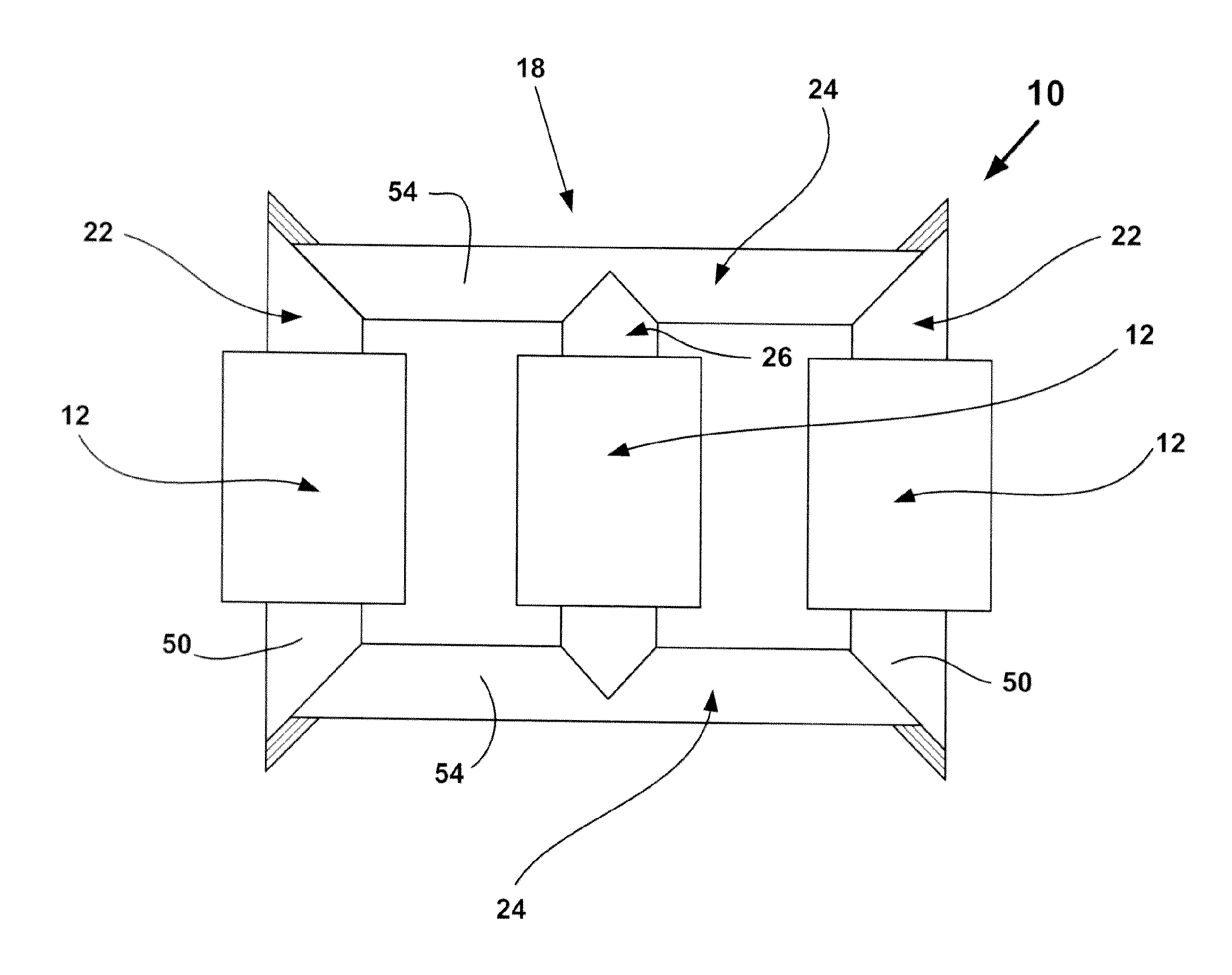
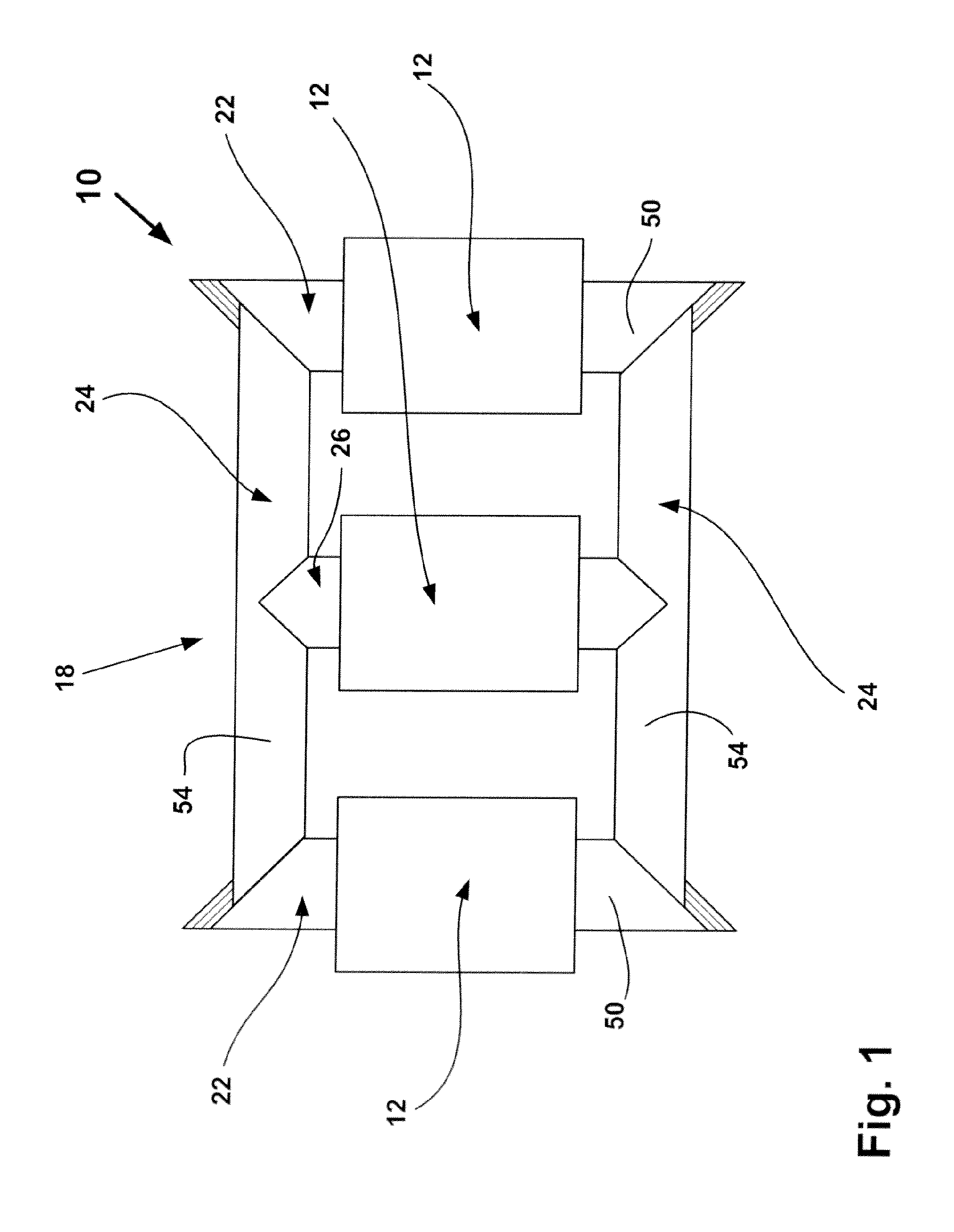
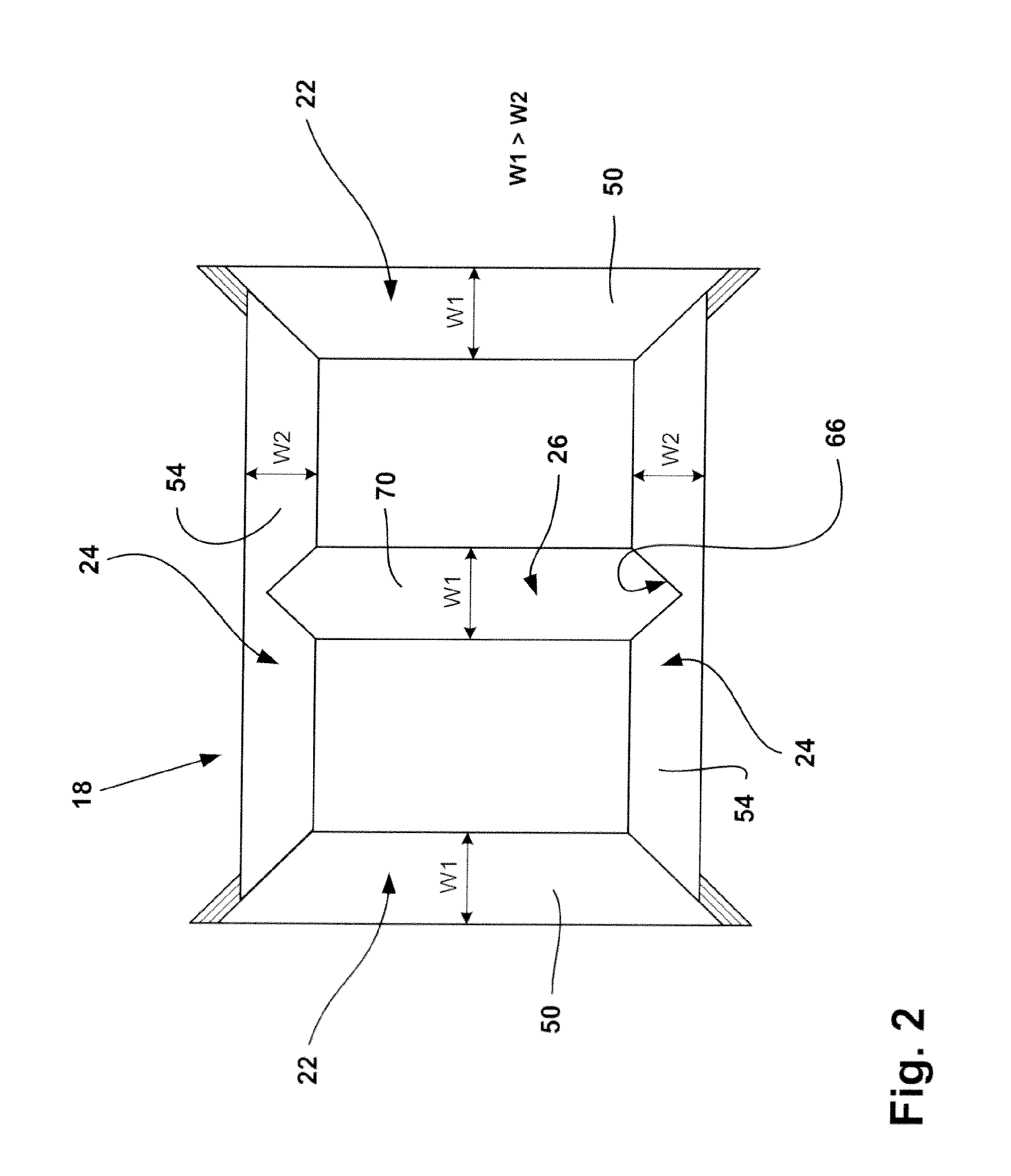
[0020]Referring now to FIG. 1, there is shown an interior view of a three-phase transformer 10 containing a stacked core embodied in accordance with the present invention. The transformer 10 comprises three winding assemblies 12 (one for each phase) mounted to a stacked core 18. The core 18 is comprised of ferromagnetic metal and is generally rectangular in shape. The core 18 includes a pair of outer legs 22 extending between a pair of yokes 24. An inner leg 26 also extends between the yokes 24 and is disposed between and is substantially evenly spaced from ...


PUM

PropertyMeasurementUnit
voltageaaaaaaaaaa
voltageaaaaaaaaaa
thicknessaaaaaaaaaa

Abstract

A transformer is provided having a stacked core with a pair of outer legs extending between a pair of yokes. The core is arranged in a plurality of layers. Each of the layers includes a pair of yoke plates and a pair of outer leg plates. In an inner-most layer, the width of each yoke plate is less than the width of each outer leg plate. In each of the layers, the inner points of the outer leg plates are substantially in contact with the yoke plates. The cross-section of the inner leg and the outer legs may be rectangular or cruciform.

Description

BACKGROUND OF THE INVENTION[0001]The invention relates to transformers and more particularly, to transformers having a stacked core and methods of making the same with reduced waste.[0002]A stacked transformer core is comprised of thin metallic laminate plates, such as grain oriented silicon steel. This type of material is used because the grain of the steel may be groomed in certain directions to reduce the magnetic field loss. The plates are stacked on top of each other to form a plurality of layers. A stacked core is typically rectangular in shape and can have a rectangular or cruciform cross-section. Examples of conventional stacked transformer cores include U.S. Pat. No. 3,157,850 to Winter; U.S. Pat. No. 4,136,322 to Maezima and U.S. Pat. No. 4,200,854 to DeLaurentis et al.[0003]The manufacture of a conventional stacked core typically results in a significant amount of steel being cut away and discarded. Therefore, it would be desirable to provide a stacked transformer core an...

Claims


Application Information

Patent Timeline
Patent Type & Authority Applications(United States)
IPC IPC(8): H01F3/02H01F41/02H01F27/245
CPCH01F27/245H01F41/0233Y10T29/49073H01F41/02H01F3/02H01F41/0206
Inventor SARVER, CHARLIEPAULEY, JR., WILLIAM E.
Owner ABB (SCHWEIZ) AG
Learn More