
Bumper beam assembly for vehicle

a bumper beam and vehicle technology, applied in the direction of bumpers, vehicle components, vehicular safety arrangments, etc., can solve the problems of increasing damage to the side member b>3/b> and the vehicle body panel, and unable to absorb crash energy sufficiently, so as to reduce the amount of crash energy, reduce damage to the main body, and increase the ability to protect the occupants

Active Publication Date: 2013-06-20
HANWHA ADVANCED MATERIALS +2
View PDF14 Cites 20 Cited by
  • Summary
  • Abstract
  • Description
  • Claims
  • Application Information

AI Technical Summary

Benefits of technology

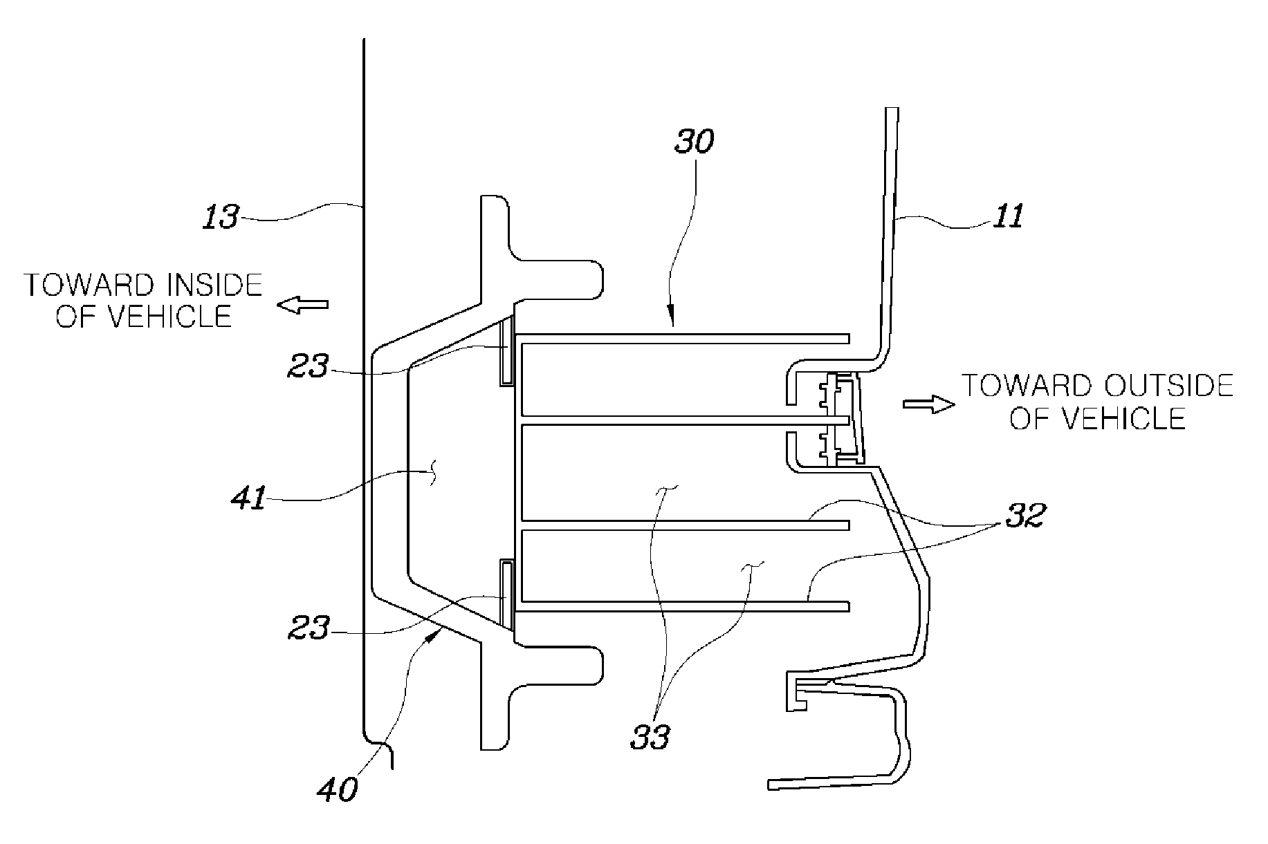
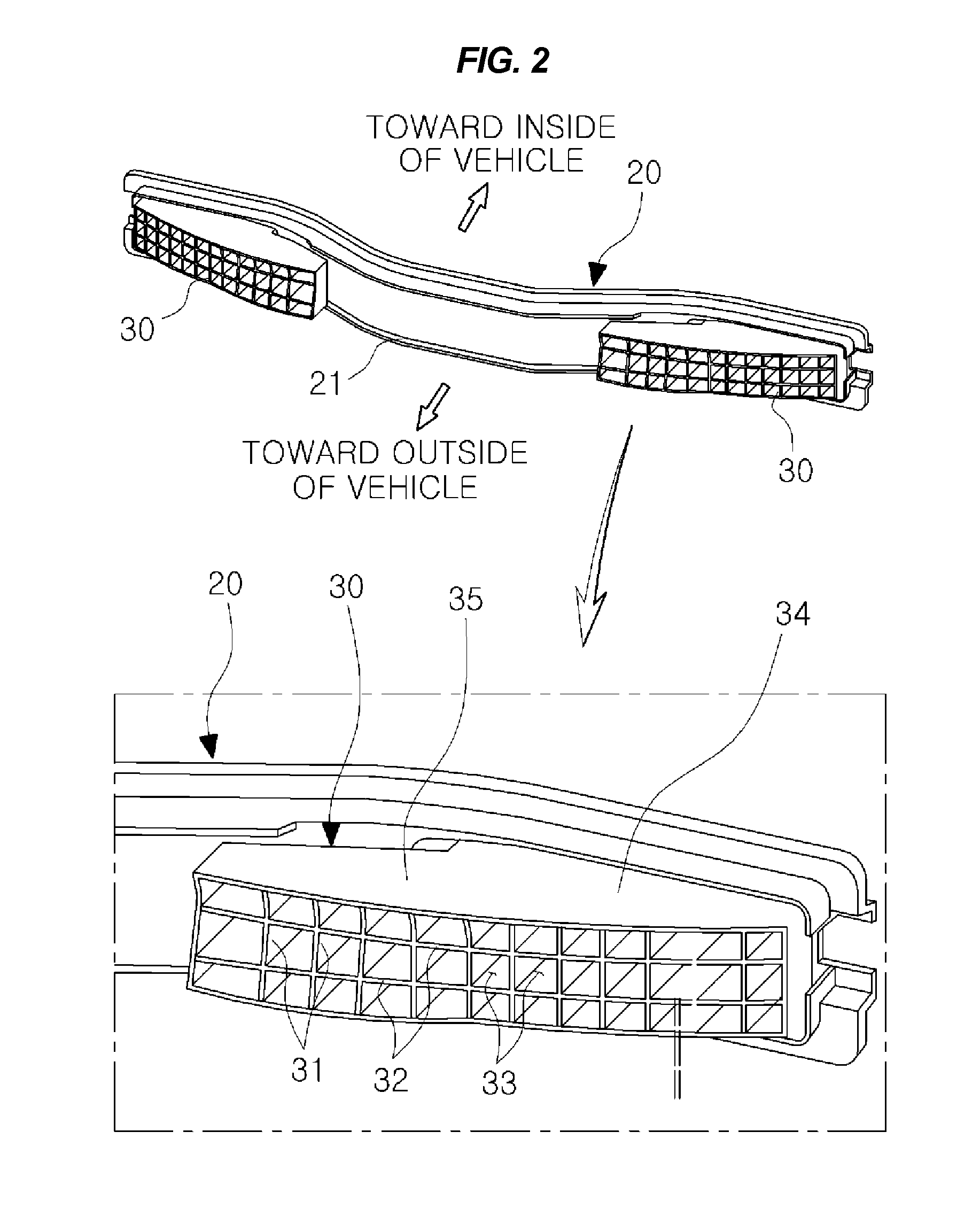
The present invention relates to a bumper beam assembly for a vehicle that can reduce the amount of crash energy transferred to the main body of the vehicle in a front or side crash, thus minimizing damage to the vehicle and increasing safety for occupants. The design of the bumper beam assembly is based on various parameters such as cross-sectional thickness, length of protrusion, outer and inner inclination angles of the back beam stays. The back beam assembly is configured to disperse and absorb crash energy, reducing the amount of damage to the vehicle body panels and side members, and improving occupant protection.

Problems solved by technology

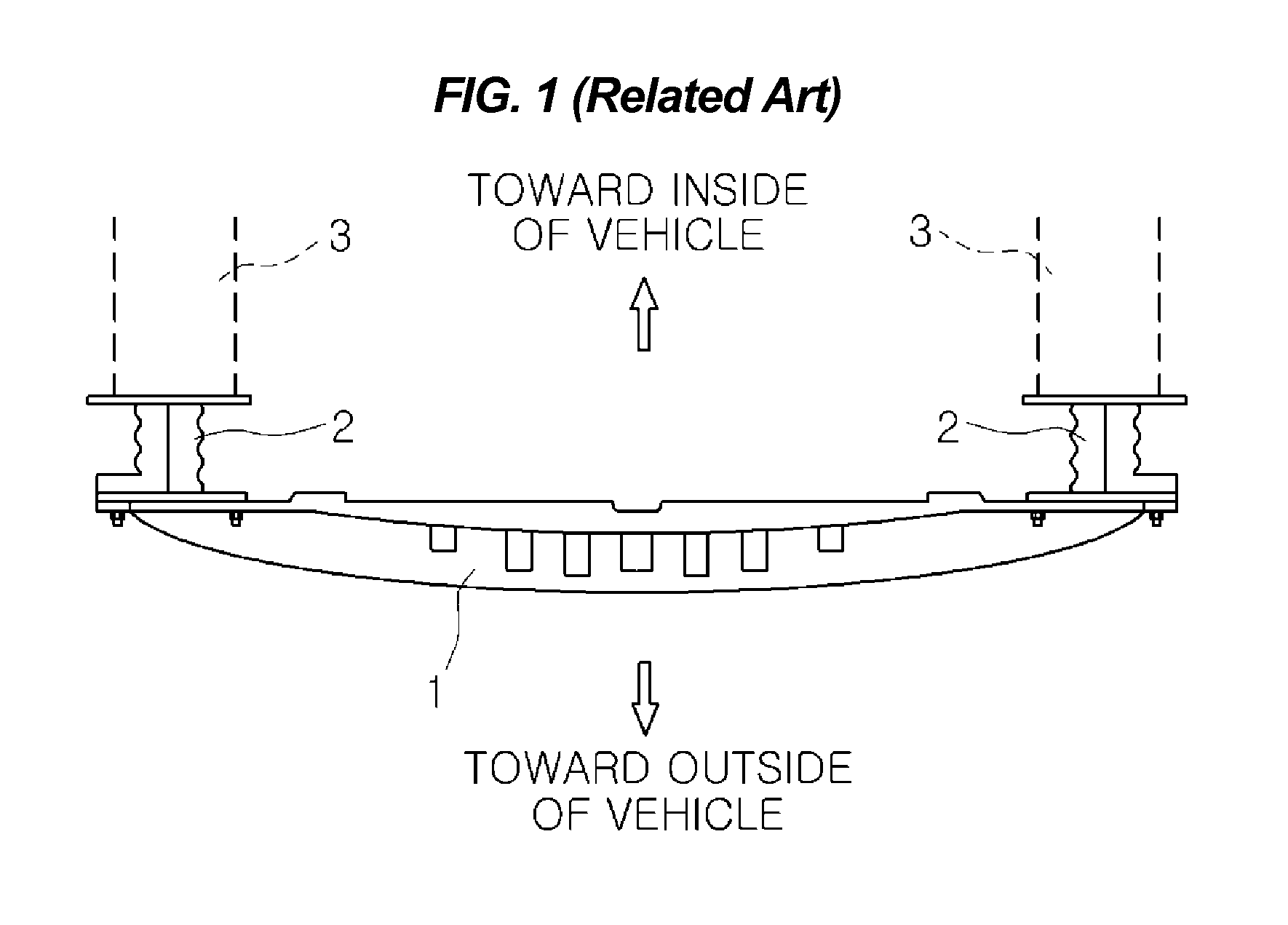
However, a drawback of the highly-rigid crash boxes 2 is that they fail to sufficiently absorb crash energy.
Consequently, as the amount of the crash energy that is transferred toward the main body of the vehicle increases, there is increased damage to the side member 3 and the vehicle body panel.

Method used


Image

  • Bumper beam assembly for vehicle
  • Bumper beam assembly for vehicle
  • Bumper beam assembly for vehicle

Examples


Embodiment Construction

[0035]Reference will now be made in detail to various embodiments of the present invention(s), examples of which are illustrated in the accompanying drawings and described below. While the invention(s) will be described in conjunction with exemplary embodiments, it will be understood that the present description is not intended to limit the invention(s) to those exemplary embodiments. On the contrary, the invention(s) is / are intended to cover not only the exemplary embodiments, but also various alternatives, modifications, equivalents and other embodiments, which may be included within the spirit and scope of the invention as defined by the appended claims.

[0036]Reference will now be made in greater detail to a bumper beam assembly for a vehicle of the invention, exemplary embodiments of which are illustrated in the accompanying drawings. Wherever possible, the same reference numerals will be used throughout the drawings and the description to refer to the same or like parts.

[0037]A...


PUM


Abstract

A bumper beam assembly for a vehicle may include a back beam disposed inside a vehicle bumper, both distal ends of the back beam being oriented in a lateral direction of a main body of the vehicle, crash boxes coupled to one side of the back beam, the crash boxes protruding from the both distal ends of the back beam toward the bumper, and back beam stays integrally coupled to the other side of the back beam, the back beam stays protruding from the both distal ends of the back beam toward an inside of the vehicle, in a direction opposite to a direction in which the crash boxes protrude.

Description

CROSS-REFERENCE TO RELATED APPLICATIONS[0001]The present application claims priority to Korean Patent Application No. 10-2011-0135549 filed on Dec. 15, 2011, the entire contents of which is incorporated herein for purposes by this reference.BACKGROUND OF THE INVENTION[0002]1. Field of the Invention[0003]The present invention relates, in general, to a bumper beam assembly for a vehicle and, more particularly, to a bumper beam assembly for a vehicle, which has excellent ability to absorb crash energy.[0004]2. Description of Related Art[0005]A bumper beam assembly is mounted on the front or rear end of a vehicle as part of an attempt to protect the main body of a vehicle as well as the occupants against a crash. As shown in FIG. 1, the bumper beam assembly of the related art includes a back beam 1 extending in the lateral direction of the main body of the vehicle, the back beam being made of glass mat reinforced thermoplastic (GMT), and crash boxes 2 coupled on both ends of the back be...

Claims


Application Information

Patent Timeline
IPC IPC(8): B60R19/34
CPCB60R19/18B60R19/34B60R2019/247B60R2019/186B60R2019/1806B60R19/24
Inventor JEONG, PHIL JUNGKU, JUN MOKIM, JIN HOLIM, JONG MYUNGNAM, SANG WOOK
Owner HANWHA ADVANCED MATERIALS
Learn More