Electrical connector

US20130157518A1Inactive Publication Date: 2013-06-20LOTES
1 Cites 3 Cited by

Patent Information

Authority / Receiving Office
US · United States
Current Assignee / Owner
Publication Date
2013-06-20
Estimated Expiration
Not applicable · inactive patent

Smart Images

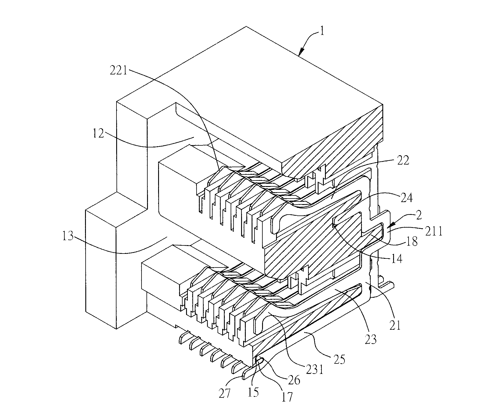
  • Figure 1
    Figure 1
  • Figure 2
    Figure 2
  • Figure 3
    Figure 3
Patent Text Reader

Abstract

An electrical connector includes an insulating body having a plurality of receiving slots and a plurality of terminals respectively fixed in the insulating body. Each of the terminals has a base at least partially disposed in the receiving slot, at least one contact arm, a first fixing portion and an extending arm extending laterally from the base, and a second fixing portion. The first fixing portion fastens the insulating body. A soldering portion is disposed on the extending arm. The second fixing portion selectively extends from the extending arm or the soldering portion and fastens the insulating body. A distance between the second fixing portion and the soldering portion is shorter than that between the first fixing portion and the soldering portion.
Need to check novelty before this filing date? Find Prior Art

Description

CROSS-REFERENCE TO RELATED APPLICATION

[0001] This non-provisional application claims priority under 35 U.S.C. §119(a) on Patent Application No. 201120520132.9 filed in P.R. China on Dec. 14, 2011, the entire contents of which are hereby incorporated by reference.

[0002] Some references, if any, which may include patents, patent applications and various publications, may be cited and discussed in the description of this invention. The citation and / or discussion of such references, if any, is provided merely to clarify the description of the present invention and is not an admission that any such reference is “prior art” to the invention described herein. All references listed, cited and / or discussed in this specification are incorporated herein by reference in their entireties and to the same extent as if each reference was individually incorporated by reference.FIELD OF THE INVENTION

[0003] The present invention relates to an electrical connector, and more particularly to an electrical c...

Examples

Embodiment Construction

[0022]The present invention is more particularly described in the following examples that are intended as illustrative only since numerous modifications and variations therein will be apparent to those skilled in the art. Various embodiments of the invention are now described in detail. Referring to the drawings, like numbers indicate like components throughout the views. As used in the description herein and throughout the claims that follow, the meaning of “a”, “an”, and “the” includes plural reference unless the context clearly dictates otherwise. Also, as used in the description herein and throughout the claims that follow, the meaning of “in” includes “in” and “on” unless the context clearly dictates otherwise. Moreover, titles or subtitles may be used in the specification for the convenience of a reader, which shall have no influence on the scope of the present invention.

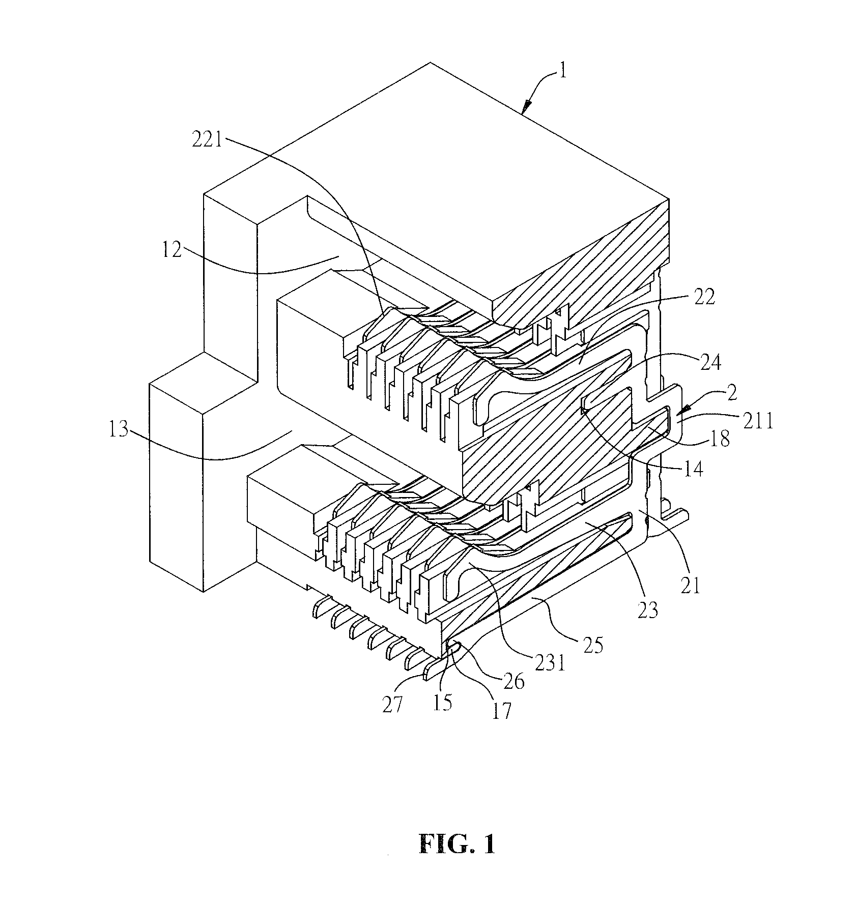
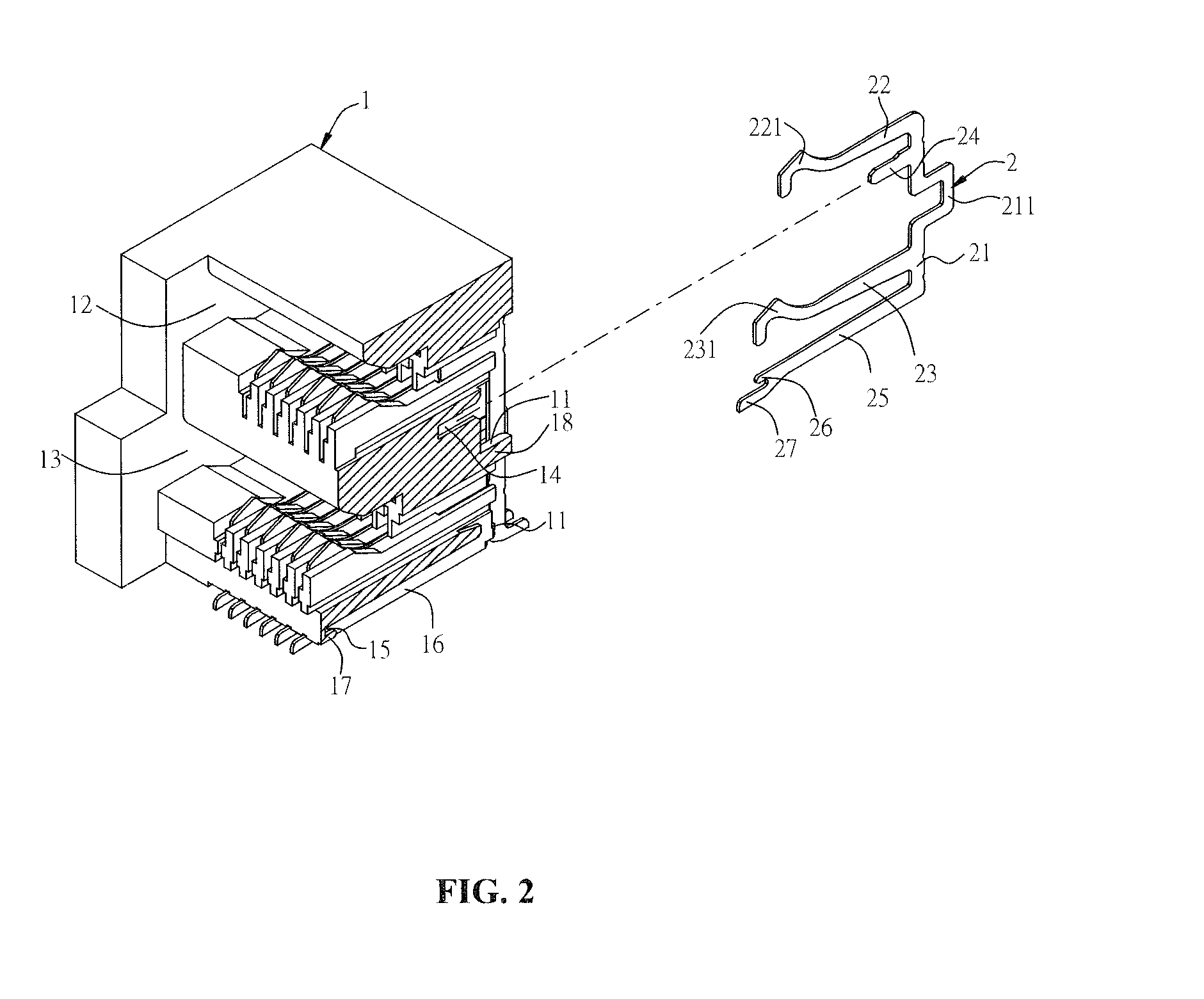
[0023]Referring to FIG. 1, an electrical connector includes an insulating body 1, and a plurality of termin...