
Guide mechanism for cylinder apparatus

Inactive Publication Date: 2006-10-19
SMC CORP
View PDF15 Cites 0 Cited by
  • Summary
  • Abstract
  • Description
  • Claims
  • Application Information

AI Technical Summary

Benefits of technology

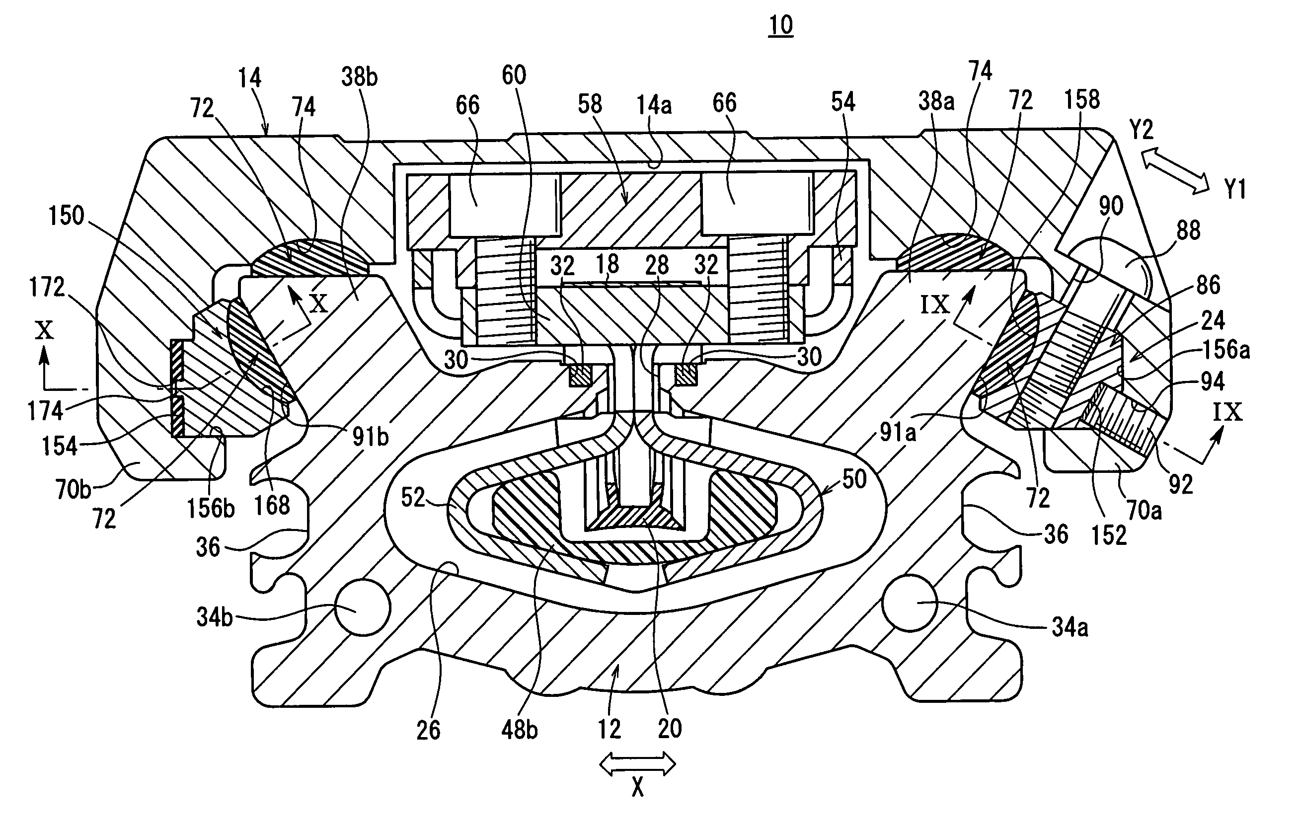
[0013] A general object of the present invention is to provide a guide mechanism for a cylinder apparatus, which makes it possible to avoid backlash of a displacement member by means of convenient adjustment mechanism, thus enabling smooth displacement of the displacement member while also improving production efficiency.

Problems solved by technology

However, generally in the case of the rodless cylinder described above, a gap that results from dimensional dispersion of respective members may appear between the main cylinder body and the slider in some situations, wherein the gap is caused by dimensional dispersion of respective members including, for example, the slider, the piston, and the main cylinder body, when they are assembled.
In such a situation, it is feared that looseness or backlash may arise when the slider is displaced along the main cylinder body.
Further, a worker having skilled techniques is required to perform the adjustment operation.
Therefore, the adjustment operation, which must be performed for each respective cylinder apparatus 1, is complicated.
Thus, production efficiency of the cylinder apparatus 1 cannot be measurably improved.

Method used


Image

  • Guide mechanism for cylinder apparatus
  • Guide mechanism for cylinder apparatus
  • Guide mechanism for cylinder apparatus

Examples


Embodiment Construction

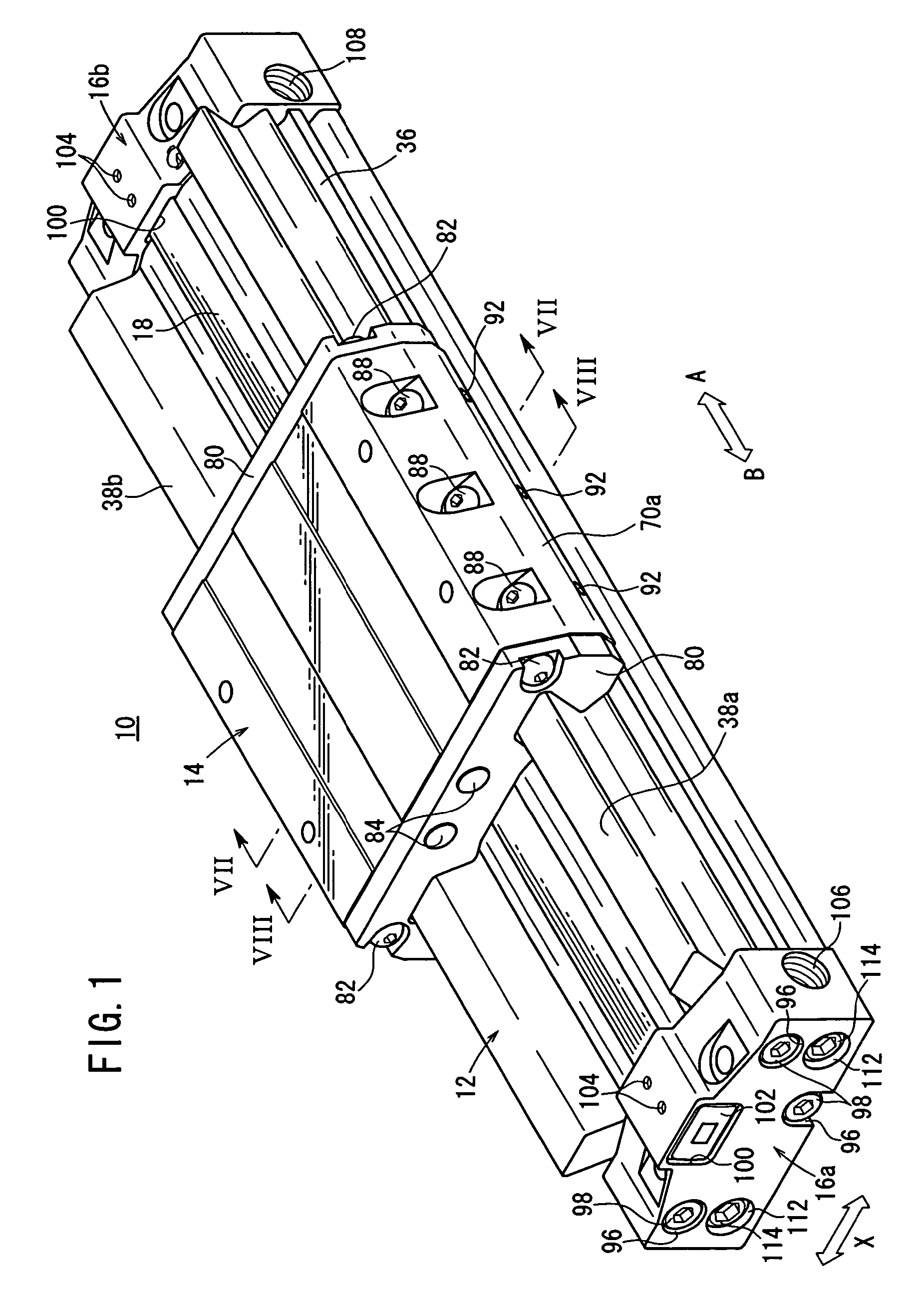
[0026] With reference to FIG. 1, reference numeral 10 indicates a cylinder apparatus to which a guide mechanism according to an embodiment of the present invention is applied.

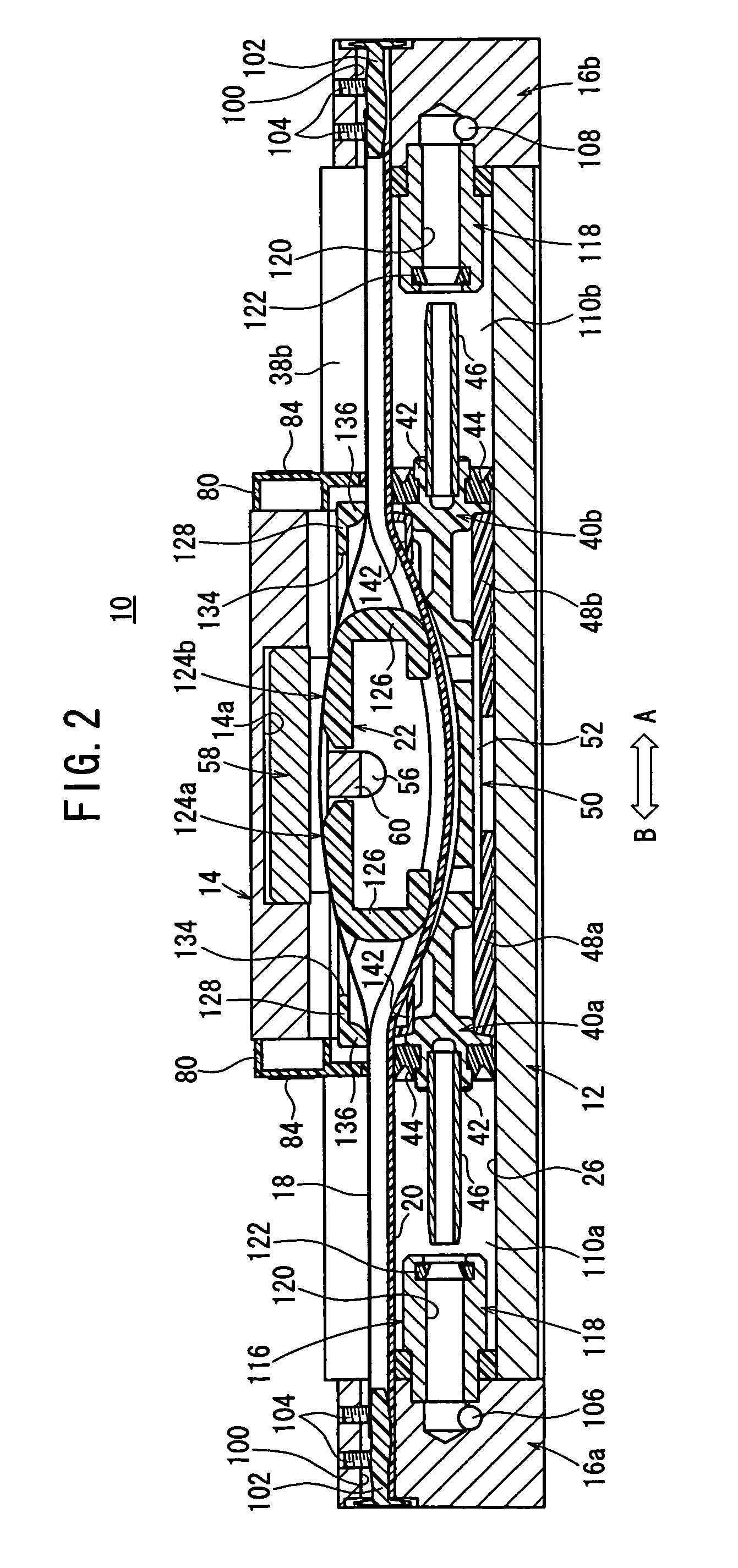
[0027] As shown in FIGS. 1 and 2, the cylinder apparatus 10 comprises a cylinder tube (main actuator body) 12, which is lengthy in the axial direction, a slider (displacement member) 14, which is attached to the cylinder tube 12 and which is movable back and forth in the axial direction, and a pair of end blocks 16a, 16b, which are installed to respective ends of the cylinder tube 12.

[0028] The cylinder apparatus 10 further comprises a belt guide mechanism 22 (see FIG. 2), which guides an upper belt 18 and a lower belt 20 (see FIGS. 7 and 8) that are installed in the cylinder tube 12, and a guide mechanism 24 (see FIGS. 7 and 8) provided between the slider 14 and the cylinder tube 12, which smoothly guides the slider 14 with respect to the cylinder tube 12.

[0029] As shown in FIGS. 3 and 7, a bore section 26,...


PUM


Abstract

A slider is displaceable in an axial direction on guide sections of a cylinder tube through a guide mechanism. A first elastic member is interposed between a first bearing support member of the guide mechanism and one retaining section of the slider. A bearing installed in the first bearing support member, is pressed continuously toward the guide section. A second bearing support member is installed via a second elastic member between the guide section and another retaining section of the slider. A bearing provided on the second bearing support member is pressed toward the guide section by means of a resilient force of the second elastic member.

Description

BACKGROUND OF THE INVENTION [0001] 1. Field of the Invention [0002] The present invention relates to a guide mechanism for a cylinder apparatus, for movably retaining and guiding a displacement member of the cylinder apparatus with respect to a main cylinder body. [0003] 2. Description of the Related Art [0004] A cylinder apparatus such as a rodless cylinder has been used as a means for transporting a workpiece. Such a rodless cylinder includes a piston, which is displaceable within a main cylinder body, and a piston yoke connected to the piston, which is exposed to the outside through a slit formed on an upper surface of the main cylinder body. A slider is installed on the piston yoke. The slider is displaced in the axial direction of the main cylinder body by displacement of the piston, in order to transport the workpiece. [0005] However, generally in the case of the rodless cylinder described above, a gap that results from dimensional dispersion of respective members may appear b...

Claims


Application Information

Patent Timeline
IPC IPC(8): F16C29/00
CPCF15B15/082F16C29/02F16C29/002F15B15/14
Inventor NARUSE, TETSUYAIIDA, KAZUHIRO
Owner SMC CORP
Learn More