Tongue depressor

a tongue depressor and tongue technology, applied in the field of tongue depressors, can solve the problems of less hygienic less use of tongue depressors, and difficulty in cleaning the blades of depressors in both u.s. pat. nos. 4,643,172 and 5,656,014

Active Publication Date: 2013-06-20
THROAT SCOPE
View PDF6 Cites 16 Cited by
  • Summary
  • Abstract
  • Description
  • Claims
  • Application Information

AI Technical Summary

Benefits of technology

[0021]Typically the blade further includes at least one depression or projection adjacent the handle to assist an operator in decoupling the blade from the handle.
[0030]Typically the blade further includes at least one depression or projection adjacent the handle, to assist an operator in decoupling the blade from the handle.
[0042]b) a blade for depressing the tongue, the blade being removably coupled to the handle, and wherein coupling the blade to the handle actuates the switch so that light emitted from the light sources is transmitted by the blade into the oral cavity, and wherein the blade includes at least one depression or projection adjacent the handle, to assist an operator in decoupling the blade from the handle.
[0097]ii) a blade for depressing the tongue, wherein the blade is removably coupled to the handle, and wherein the blade includes at least one depression or projection adjacent the handle, to assist an operator in decoupling the blade from the handle and wherein light emitted from the light source is transmitted by the blade into the oral cavity;
[0104]ii) a blade for depressing the tongue, wherein the blade is removably coupled to the handle, and wherein the blade includes at least one depression or projection adjacent the handle, to assist an operator in decoupling the blade from the handle and wherein coupling the blade to the handle actuates the switch so that light emitted from the light sources is transmitted by the blade into the oral cavity;

Problems solved by technology

The use of a sheath in both U.S. Pat. Nos. 4,643,172 and 5,656,014 may be disadvantageous.
Furthermore, while the sheath may be sterile the depressor blade may require cleaning.
This may make these tongue depressors less hygienic and more difficult to use.
It may be difficult to provide sufficient light contrast when using a wooden spatula and a torch, or with a lamp positioned towards the end of the depressor blade as in U.S. Pat. No. 5,656,014.
A relatively complex blade decoupling mechanism is provided in this tongue depressor, complicating manufacturing.
Furthermore, the handle includes a large number of components which may also complicate manufacturing.

Method used


Image

  • Tongue depressor
  • Tongue depressor
  • Tongue depressor

Examples


Embodiment Construction

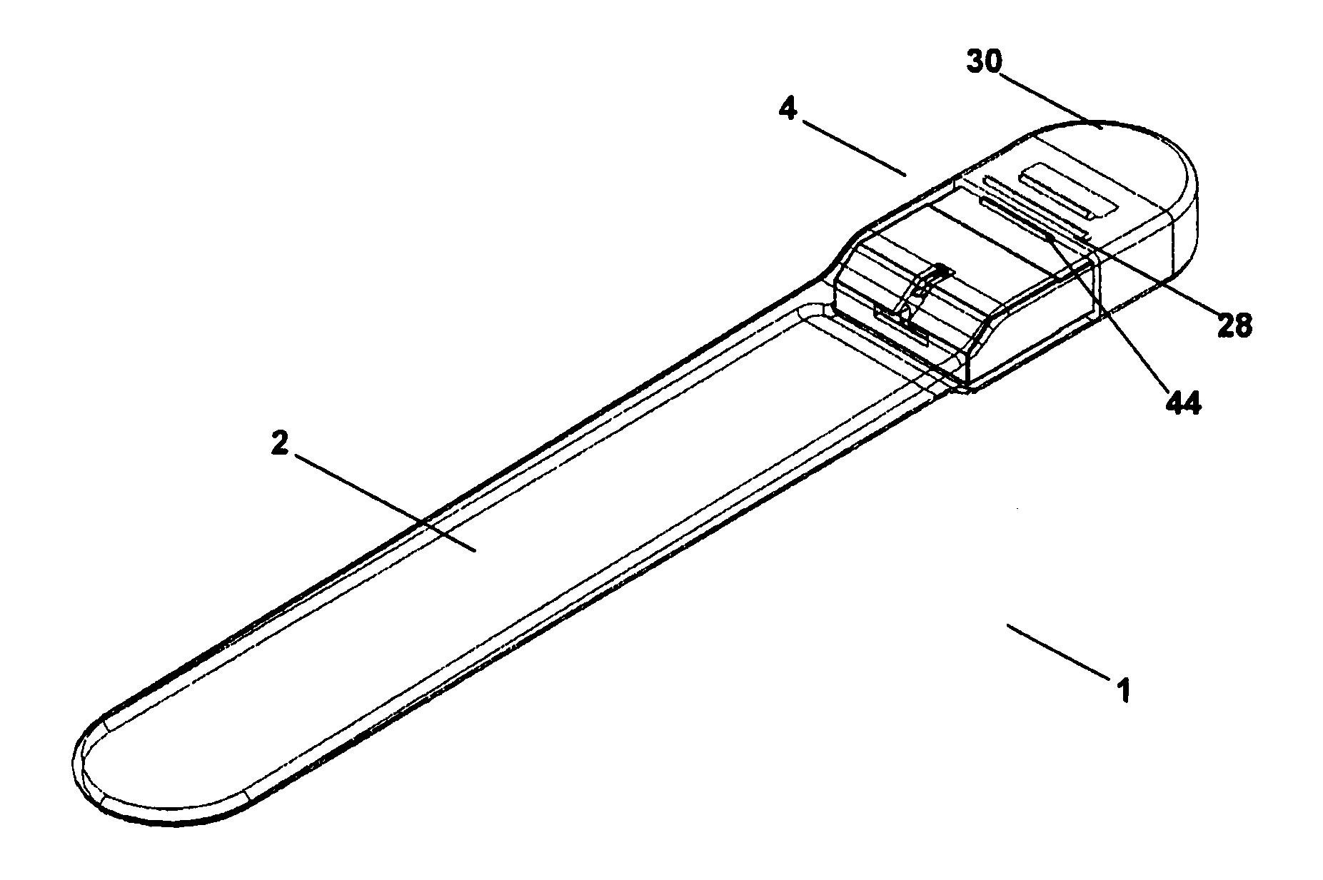
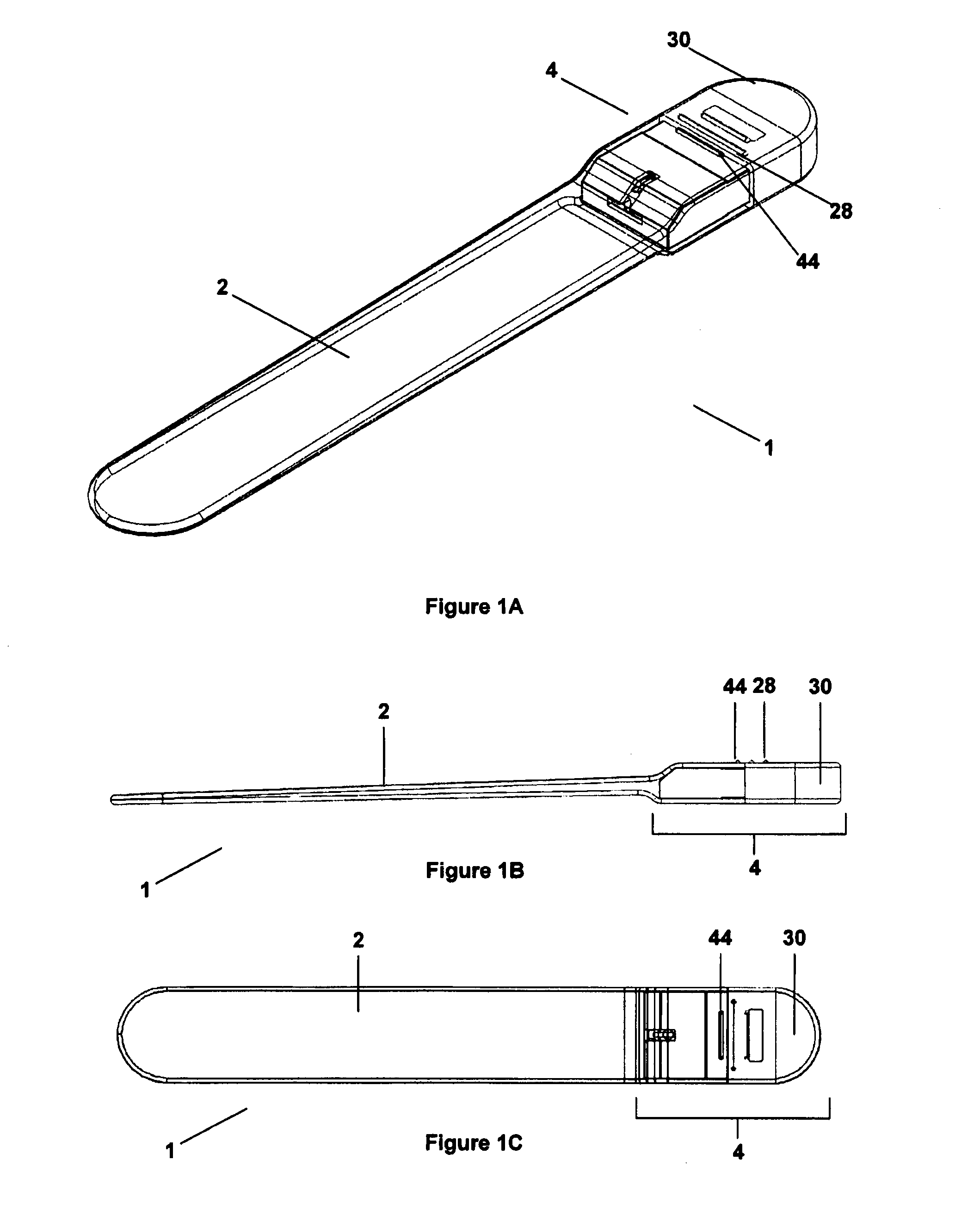
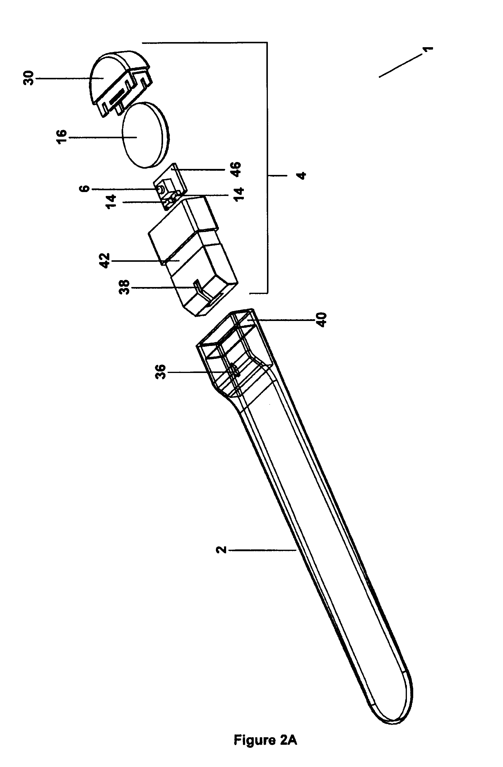
[0140]Example tongue depressors for illuminating an oral cavity will now be described with reference to FIGS. 1 to 8.

[0141]FIGS. 1 and 2 illustrate a tongue depressor 1 which includes a blade 2, and a handle 4. The blade 2 is configured to removably couple to the handle 4. The handle includes a light source 14, and the tongue depressor 1 is configured so that light emitted from the light source 14 is transmitted by the blade 2 into the oral cavity, when the handle 4 and blade 2 are coupled together. FIG. 3 illustrates part of handle 4, and FIG. 4 illustrates blade 2.

[0142]When the tongue depressor is used by an operator, it may be held by handle 4, and the blade 2 may be used to depress the tongue. Light emitted from the light source 14 is transmitted through the blade 2 and illuminates the oral cavity. Accordingly, the term “blade”, as used herein, relates to the portion of the tongue depressor which may be used to depress the tongue of a subject. In one example, the blade is subst...


PUM


Abstract

A tongue depressor for illuminating an oral cavity, the tongue depressor including a handle which includes a light source and a switch for connecting a power supply to the light source. The tongue depressor also includes a blade for depressing the tongue, the blade being removably coupled to the handle, and wherein coupling the blade to the handle actuates the switch so that light emitted from the light source is transmitted by the blade into the oral cavity.

Description

FIELD OF THE INVENTION[0001]The present invention relates to a tongue depressor for illuminating the oral cavity, and to methods of using the tongue depressor.BACKGROUND OF THE INVENTION[0002]The reference in this specification to any prior publication (or information derived from it), or to any matter which is known, is not, and should not be taken as an acknowledgment or admission or any form of suggestion that that prior publication (or information derived from it) or known matter forms part of the common general knowledge in the field of endeavour to which this specification relates.[0003]Medical personnel generally use a wooden spatula in one hand to depress the tongue of a subject when examining the oral cavity. To provide adequate illumination for the examination, the medical personnel must also direct light into the oral cavity, which generally involves the use of the other hand. The use of both hands can present difficulties for medical personnel as it may be advantageous t...

Claims


Application Information

Patent Timeline
Patent Type & Authority Applications(United States)
IPC IPC(8): A61B1/24A61B1/06A61B1/00A61B1/32A61B1/07
CPCA61B13/00A61B1/00066A61B1/00121A61B1/32A61B1/07A61B1/24A61B1/0684
Inventor HOLLAND, JENNIFER LOUISE
Owner THROAT SCOPE
Why Eureka
Try Eureka