Home monitoring settings based on weather forecast

a technology for home monitoring and weather forecasts, applied in computer control, adaptive control, instruments, etc., can solve problems such as the optimal temperature of the user's selected set of settings

Active Publication Date: 2013-06-20
VERIZON PATENT & LICENSING INC
View PDF12 Cites 58 Cited by
  • Summary
  • Abstract
  • Description
  • Claims
  • Application Information

AI Technical Summary

Problems solved by technology

However, the user's selected set temperature may not be optimal.

Method used


Image

  • Home monitoring settings based on weather forecast
  • Home monitoring settings based on weather forecast
  • Home monitoring settings based on weather forecast

Examples


Embodiment Construction

[0012]The following detailed description refers to the accompanying drawings. The same reference numbers in different drawings identify the same or similar elements.

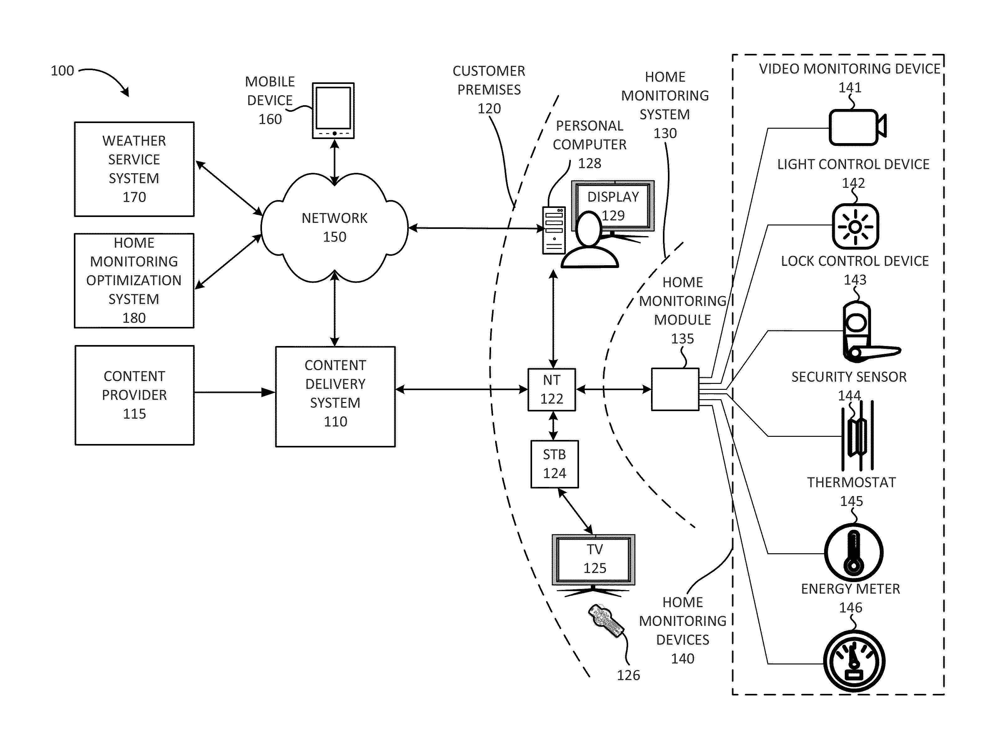
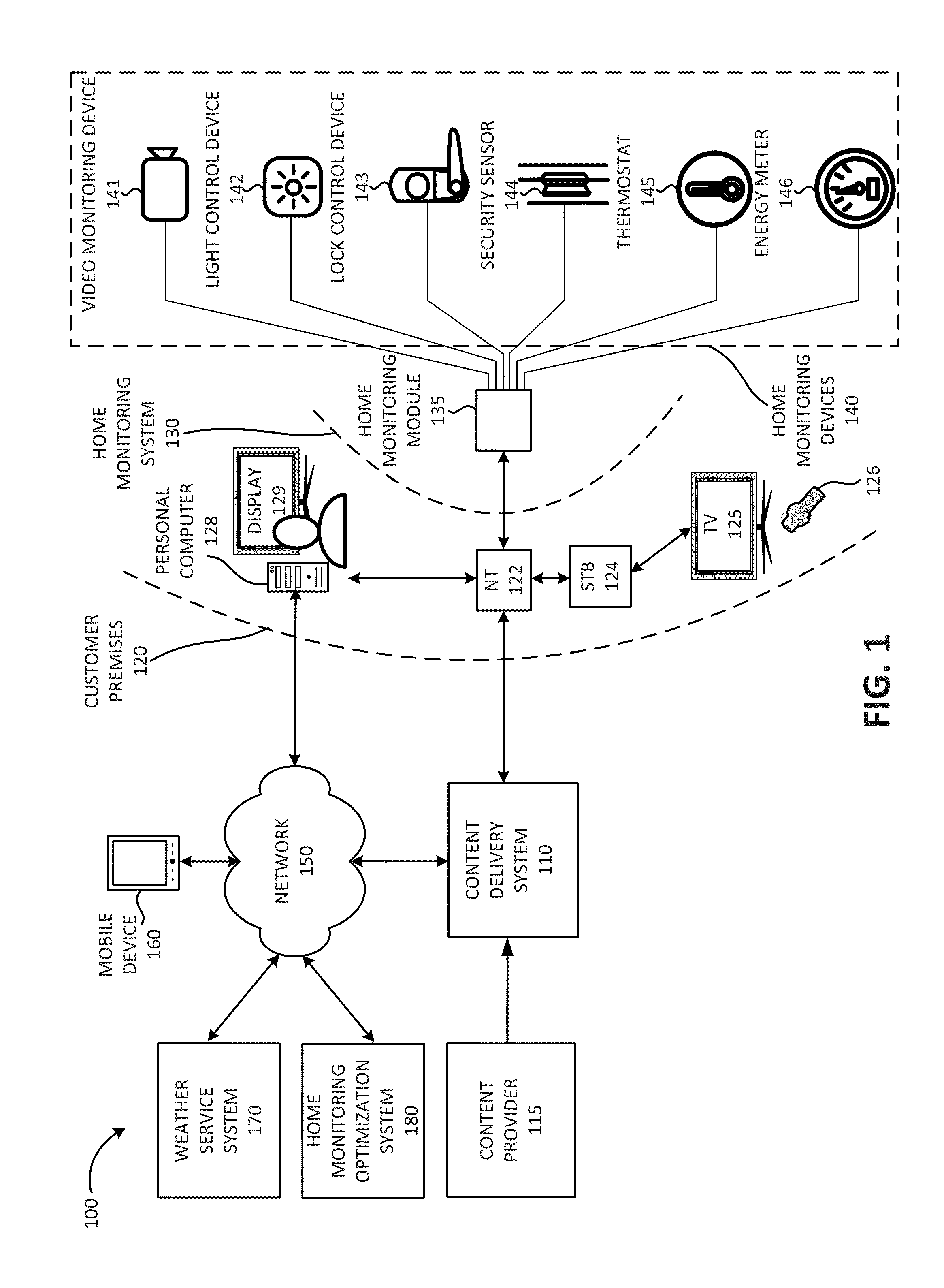
[0013]A customer may program a thermostat to a desired temperature. The thermostat may include a temperature sensor that measures air temperature and may maintain the customer's home (referred to herein as “customer premises”) at the desired temperature by measuring the air temperature inside the home. However, the air temperature may not accurately correlate to thermal comfort, because thermal comfort may depend on other factors. For example, thermal comfort may also depend on the mean radiant temperature of the walls, floor, and ceiling of the home. A mean radiant temperature that is lower than the air temperature may cause an occupant of the home to radiate heat to the walls, floor, and ceiling of the home, leading to lower thermal comfort. Furthermore, the enclosures of the home may take significantly longer to heat ...


PUM


Abstract

A system may include a set-top box, associated with a customer premises, configured to receive a television signal and provide the television signal to a television and a home monitoring device configured to obtain a weather forecast for a geographic area associated with the customer premises, determine a thermostat setting for the customer premises based on the obtained weather forecast, and provide a recommendation about the determined thermostat setting to the set-top box. The set-top box may be further configured to present the recommendation about the determined thermostat setting via the television; receive a selection of the determined thermostat setting; and provide an indication of the selection to the home monitoring device; and the home monitoring device may be further configured to apply the determined thermostat setting to a thermostat controller associated with the customer premises, in response to receiving the indication from the set-top box.

Description

BACKGROUND INFORMATION[0001]A user may install a home monitoring system that includes a thermostat. The thermostat may maintain a set temperature in the user's home by controlling a heating system and / or a cooling system. For example, if the temperature inside the home drops below the set temperature, the thermostat may activate a heating system to raise the temperature to the set temperature. The user may select a particular set temperature for the thermostat. However, the user's selected set temperature may not be optimal.BRIEF DESCRIPTION OF THE DRAWINGS[0002]FIG. 1 is a diagram illustrating an exemplary environment according to an implementation described herein;[0003]FIG. 2 is a diagram illustrating exemplary components of a device of FIG. 1;[0004]FIG. 3 is a diagram illustrating exemplary functional components of the home monitoring module of FIG. 1;[0005]FIG. 4 is a diagram illustrating exemplary components of the settings memory of FIG. 3;[0006]FIG. 5 is a diagram illustrati...

Claims


Application Information

Patent Timeline
Patent Type & Authority Applications(United States)
IPC IPC(8): G05D23/00
CPCG05D23/1917
Inventor SOMASUNDARAM, POOTHABALANSUNDARAM, KRISHNAKUMARRAMASAMY, GANESHPALANIVELU, THAMILENTHISURULINATHAN, ARUNKUMARFELIX, PRADEEPSIVARAMAN, SUNDAR
Owner VERIZON PATENT & LICENSING INC
Why Eureka
Try Eureka