Check patentability & draft patents in minutes with Patsnap Eureka AI!

Hydraulic shovel operability range display device and method for controlling same

a display device and hydraulic shovel technology, applied in the direction of process and machine control, program control, instruments, etc., can solve the problems of slipping tip of the dug ground surface slipping,

Active Publication Date: 2013-06-20
KOMATSU LTD
View PDF8 Cites 32 Cited by
  • Summary
  • Abstract
  • Description
  • Claims
  • Application Information

AI Technical Summary

Benefits of technology

The present invention relates to a hydraulic shovel operability range display device and a method for controlling it. The technical effect of the invention is that it allows for an appropriate operability range to be displayed even when the orientation of the vehicle body is tilted. By correcting the boundary between the operability range and the underbody area so that the angle formed by the boundary and the ground surface on which the vehicle body is positioned is at least 90° when the vehicle body is tilted backwards, the tip of the dug ground surface is kept from forming an acute angle. This results in improved visibility and efficiency during digging operations.

Problems solved by technology

When digging is performed according to such operability range, the tip of the dug ground surface is liable to crumble.

Method used


Image

  • Hydraulic shovel operability range display device and method for controlling same
  • Hydraulic shovel operability range display device and method for controlling same
  • Hydraulic shovel operability range display device and method for controlling same

Examples


Embodiment Construction

1. Configuration

1-1. Overall Configuration of Hydraulic Shovel

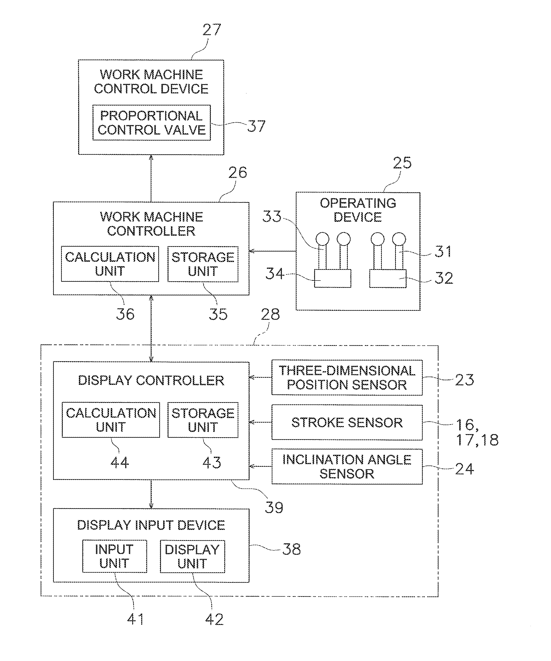
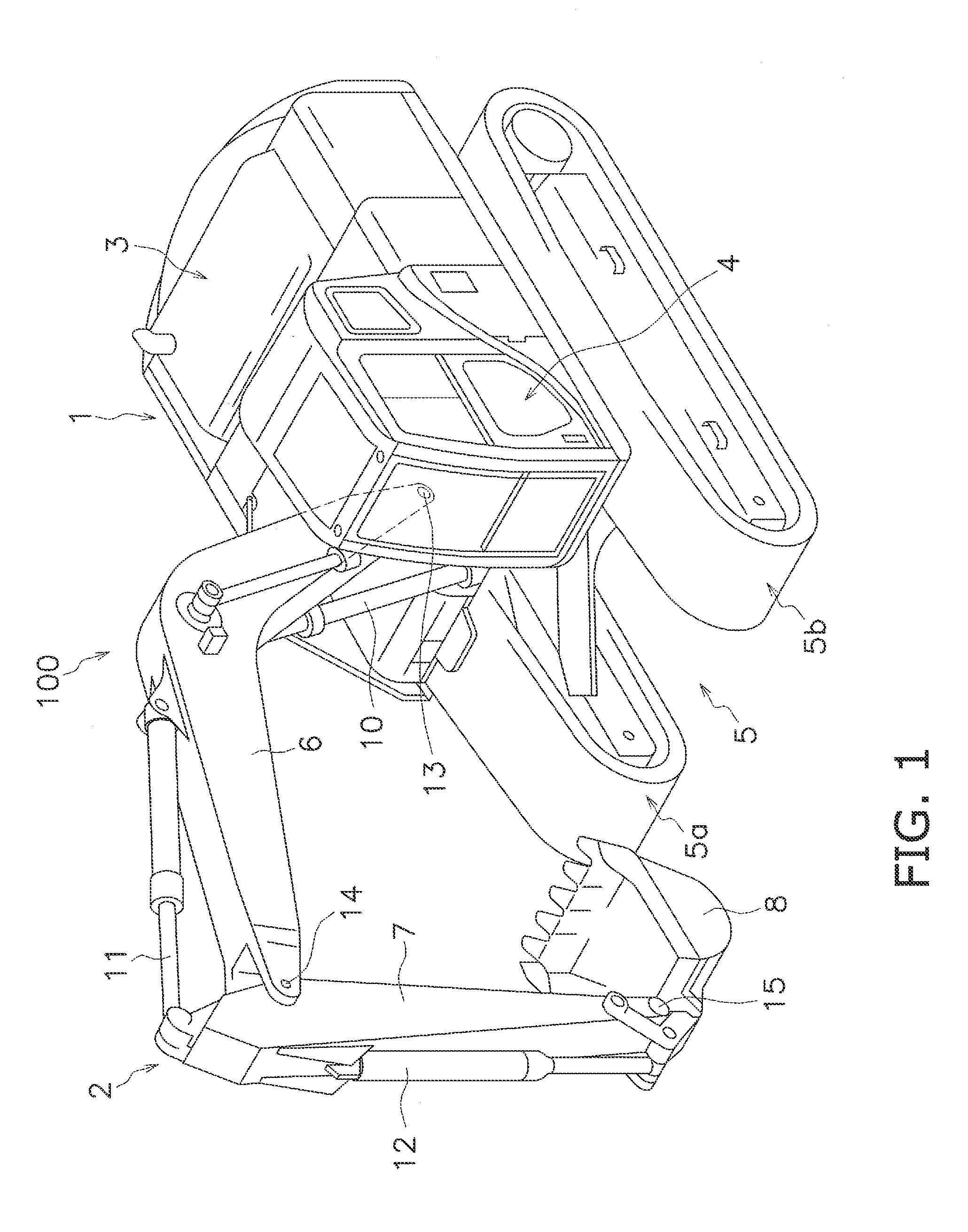
[0026]There follows a description of a hydraulic shovel operability range display device according to an embodiment of the present invention with reference to the drawings. FIG 1 is a perspective view of a hydraulic shovel 100 in which an operability range display device is installed. The hydraulic shovel 100 has a main vehicle body 1 and a work machine 2. The main vehicle body 1 has an upper pivoting body 3, a cab 4, and a travel unit 5. The upper pivoting body 3 includes devices, such as an engine, a hydraulic pump, and the like, which are not shown in the drawings. The cab 4 is installed on the front of the upper pivoting body 3. A display input device 38 and an operating device 25 described below are disposed within the cab 4 (cf. FIG. 3). The travel unit 5 has tracks 5a, 5b, and the rotation of the tracks 5a, 5b causes the hydraulic shovel 100 to travel.

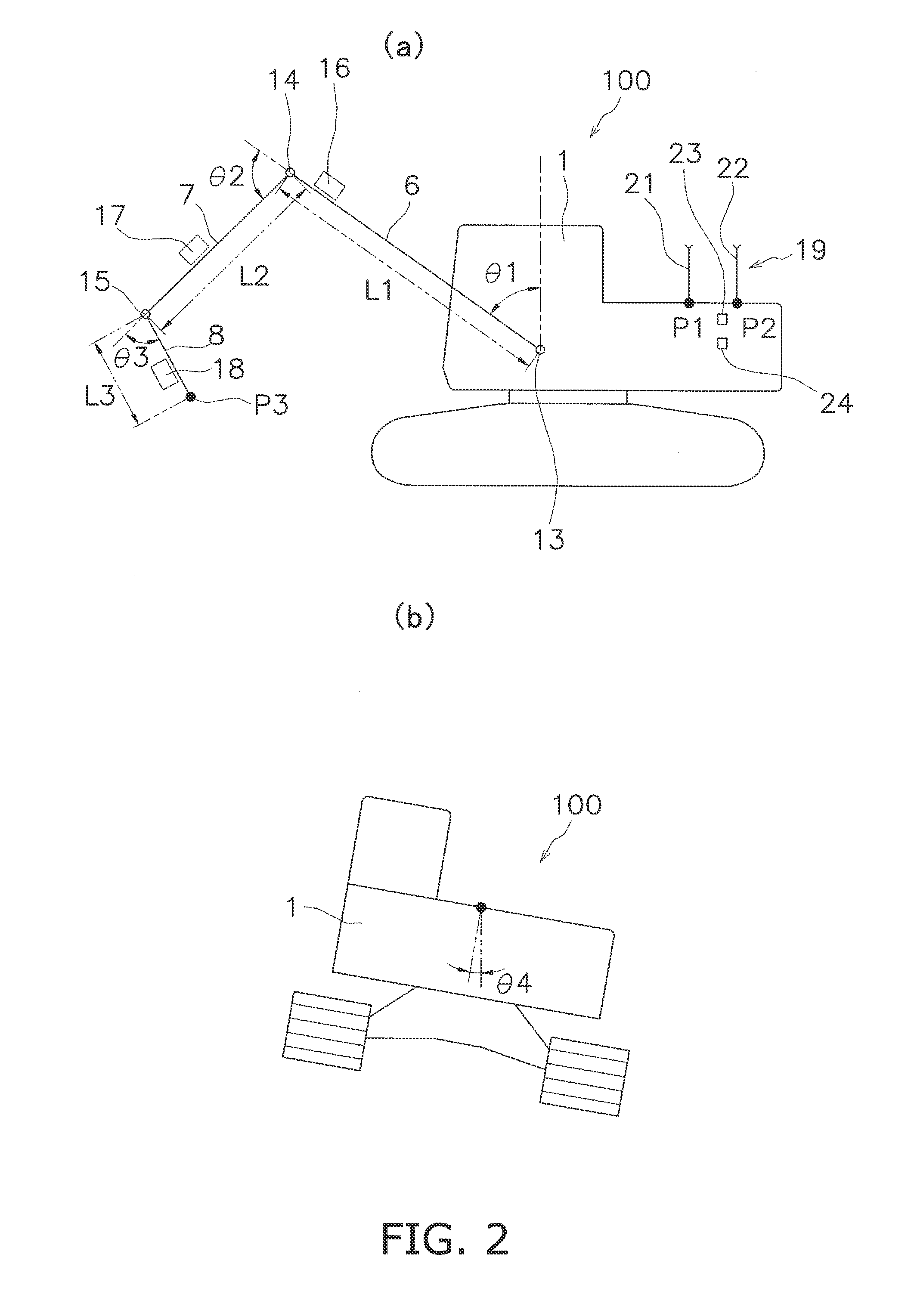
[0027]The work machine 2 is attached to the front of the main ve...


PUM


Abstract

In a hydraulic shovel operability range display device, a calculation unit is configured to set a boundary between an operability range and an underbody area along a vertical direction in a global coordinate system when a vehicle body is horizontally oriented. When the vehicle body is tilted forward, the calculation unit is configured to set the boundary so as to be maintained along the vertical direction in the global coordinate system. When the vehicle body is tilted backwards, the calculation unit is configured to correct the boundary between the operability range and the underbody area so that an angle formed by the boundary and the ground surface on which the vehicle body is positioned is at least 90°.

Description

CROSS-REFERENCE TO RELATED APPLICATIONS[0001]This application claims priority to Japanese Patent Application No. 2011-036199 filed on Feb. 22, 2011, the disclosure of which is hereby incorporated herein by reference in its entirety.TECHNICAL FIELD[0002]The present invention relates to a hydraulic shovel operability range display device and a method for controlling same.BACKGROUND ART[0003]Conventionally, an operability range display device for displaying the range that a work machine is capable of reaching is known. For example, Japanese Laid-open Patent Application Publication 2001-98585 discloses a digging work guidance device. The guidance device displays a side view of a hydraulic shovel and a cross section of a design land shape constituting a work object on a screen. An operability range showing the range of motion of a bucket is also displayed on the screen.[0004]Meanwhile, Japanese Laid-open Utility Model Application Publication H2-30521 discloses a safety device for a diggi...

Claims


Application Information

Patent Timeline
IPC IPC(8): E02F9/26
CPCE02F9/2033E02F9/26E02F9/2037G05B2219/45012E02F9/262E02F9/264E02F9/20
Inventor FUKANO, RYOASADA, HISASHIKURIHARA, TAKASHI
Owner KOMATSU LTD
Features
  • R&D
  • Intellectual Property
  • Life Sciences
  • Materials
  • Tech Scout
  • Unparalleled Data Quality
  • Higher Quality Content
  • 60% Fewer Hallucinations
Learn More