
Lens for uniform illumination

Inactive Publication Date: 2013-06-27
DONGGUAN LEDLINK OPTICS +2
View PDF6 Cites 8 Cited by
  • Summary
  • Abstract
  • Description
  • Claims
  • Application Information

AI Technical Summary

Benefits of technology

The present invention provides a lens that can evenly spread out light from an LED. This lens reduces the loss of brightness from the surface of the LED. This results in a better and more complete spreading of light, which improves the overall efficiency of the LED.

Problems solved by technology

However, since the light emitting area of the LED is small and the light from the LED is generally a point source of light, a uniform luminance can hardly be achieved.
This limits the utilization of the LED.
Unfortunately, the light output from the emitting surface of the light guide component is undesirably attenuated and the light of the LED cannot be spread efficiently.
Therefore, the conventional light guide component applied in the LED still cannot solve the problem of the non-uniformity of the LED.

Method used


Image

  • Lens for uniform illumination
  • Lens for uniform illumination
  • Lens for uniform illumination

Examples


Embodiment Construction

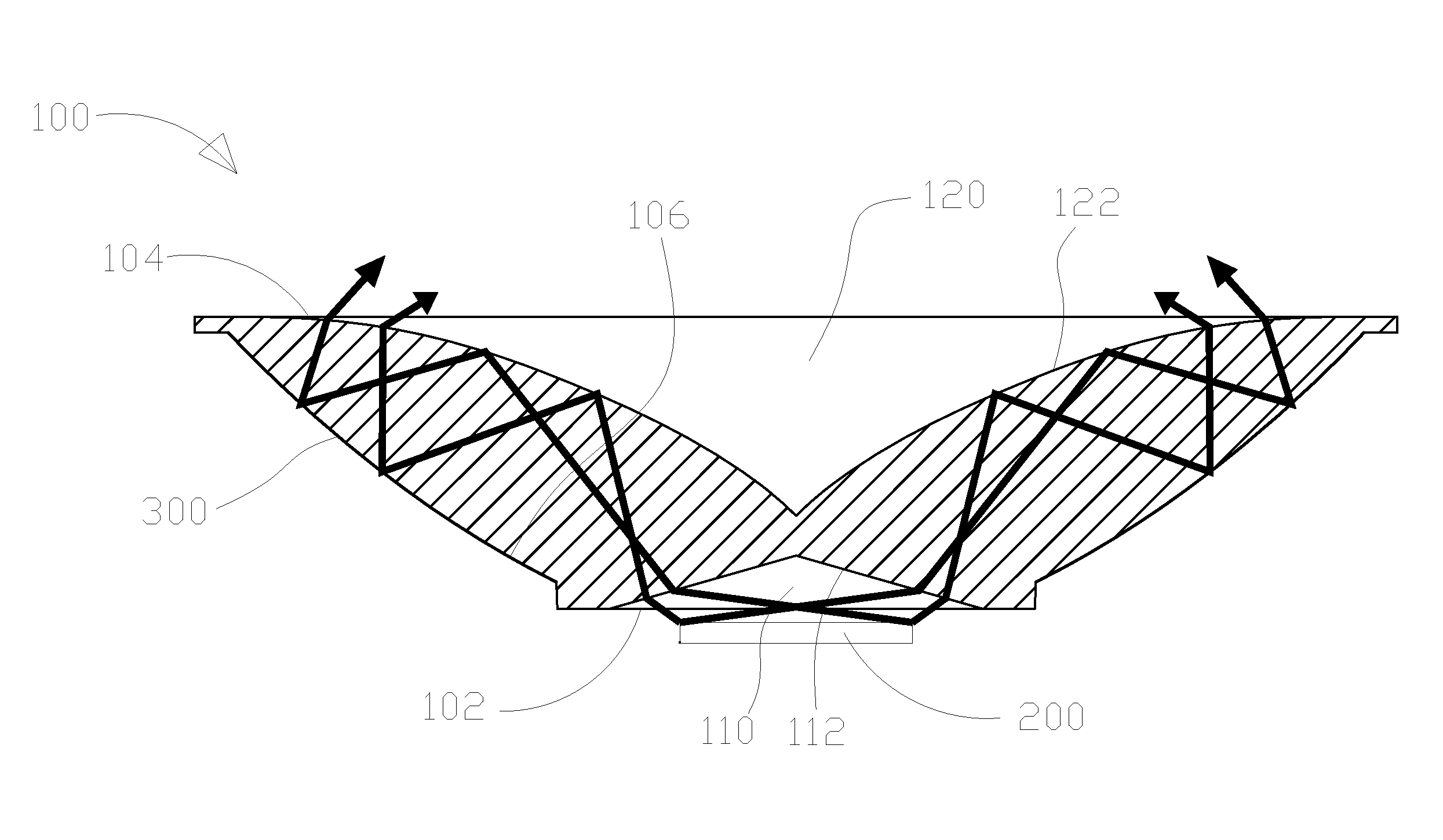
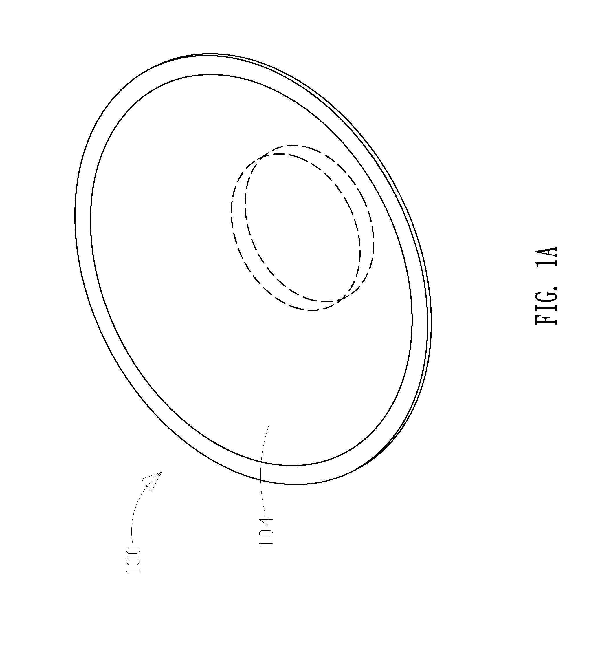
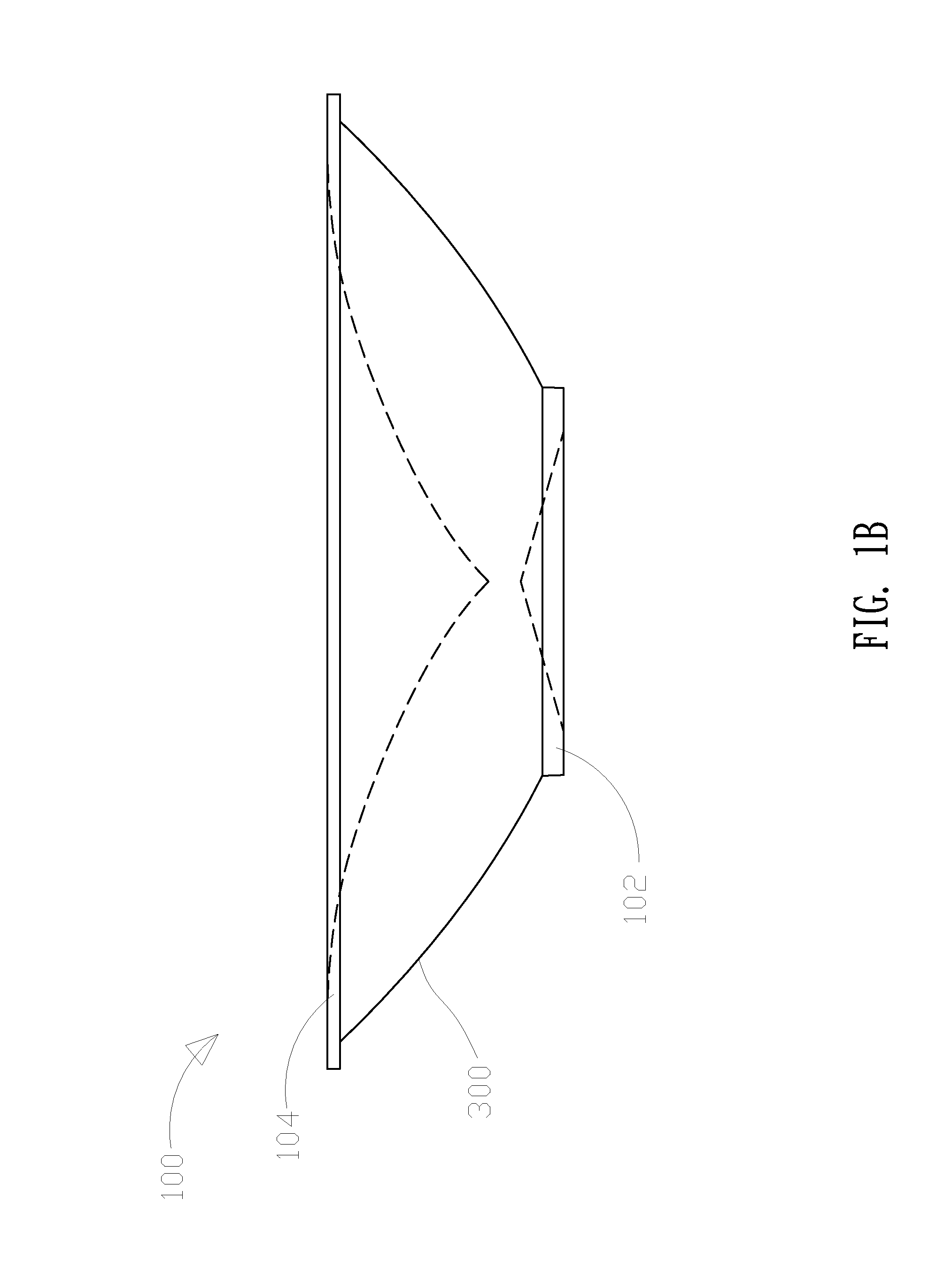
[0023]FIGS. 1A to 1D are respectively a 3-dimensional view, side view, vertical view and sectional view of FIG. 1C taken along the A-A line of the lens in a first preferred embodiment of the present invention.

[0024]As shown in the figures, the lens in the first preferred embodiment is implemented in a light source 200 which is a light-emitting diode (LED). The LED outputs light from the side surface, but a person having ordinary skill in the art can change the type of the light source 200 in accordance with the practical requirement and it is not limited herein.

[0025]The lens in the present embodiment includes a light guide body 100 and a reflector 300. The light guide body 100 is made of acrylic, glass or any other organic translucent material that facilitates the transmittal or refraction of the light. The light guide body 100 includes an incident surface 102, an emitting surface 104 that is opposite to the incident surface 102, a side surface 106 surrounding the light guide body ...


PUM


Abstract

A lens for uniform illumination for a light source includes a light guide body and a reflector. The light guide body includes a side surface, an incident surface and an emitting surface opposite to the incident surface, a trough next to the incident surface having a first wall, and a tapered space next to the emitting surface having a second wall. When the light source emits light, the light is refracted from a first wall of the trough to a second wall of the tapered space. The light is totally reflected by the second wall, travels to the side surface, and is reflected by the reflector over the second wall, then refracted at the second wall to pass through the light guide body. Therefore, the light from the light source is spread out effectively and the luminous efficiency of the light source is enhanced.

Description

[0001]This application claims the benefit of the filing date of Taiwan Patent Application No. 100147911, filed on Dec. 22, 2011, in the Taiwan Intellectual Property Office, the disclosure of which is incorporated herein in its entirety by reference.BACKGROUND OF THE INVENTION[0002]1. Field of the Invention[0003]The present invention relates to an optical device, and more particularly relates to a lens with total reflection.[0004]2. Description of the Prior Art[0005]A lighting equipment is necessary in our daily life and the lighting equipment with better illuminance and lower power consumption has been developed as the technology advances. Now, the most popular light source is Light-Emitting Diode (LED) which is also a semiconductor component. The LED which generates cold light is energy saving, eco-friendly and featured by a long life cycle, low heat generation and no ultraviolet ray irradiation. Therefore, LED would gradually replace the traditional light source.[0006]Due to the p...

Claims


Application Information

Patent Timeline
IPC IPC(8): F21V13/04
CPCF21V13/04F21Y2101/02F21V7/0091F21Y2115/10
Inventor TANG, TE LUNG
Owner DONGGUAN LEDLINK OPTICS
Learn More