
Automated insertion and extraction of an implanted biosensor

a biosensor and automatic technology, applied in the field of automatic insertion and extraction of biosensors, can solve the problems of inoperable biosensors, reduced photovoltaic cells' effective absorption area, misalignment of on-board leds, etc., to facilitate pain-free injection, minimize cost, and optimize optical powering and communication protocols

Inactive Publication Date: 2017-02-02
OPTOELECTRONICS SYST CONSULTING
View PDF0 Cites 6 Cited by
  • Summary
  • Abstract
  • Description
  • Claims
  • Application Information

AI Technical Summary

Benefits of technology

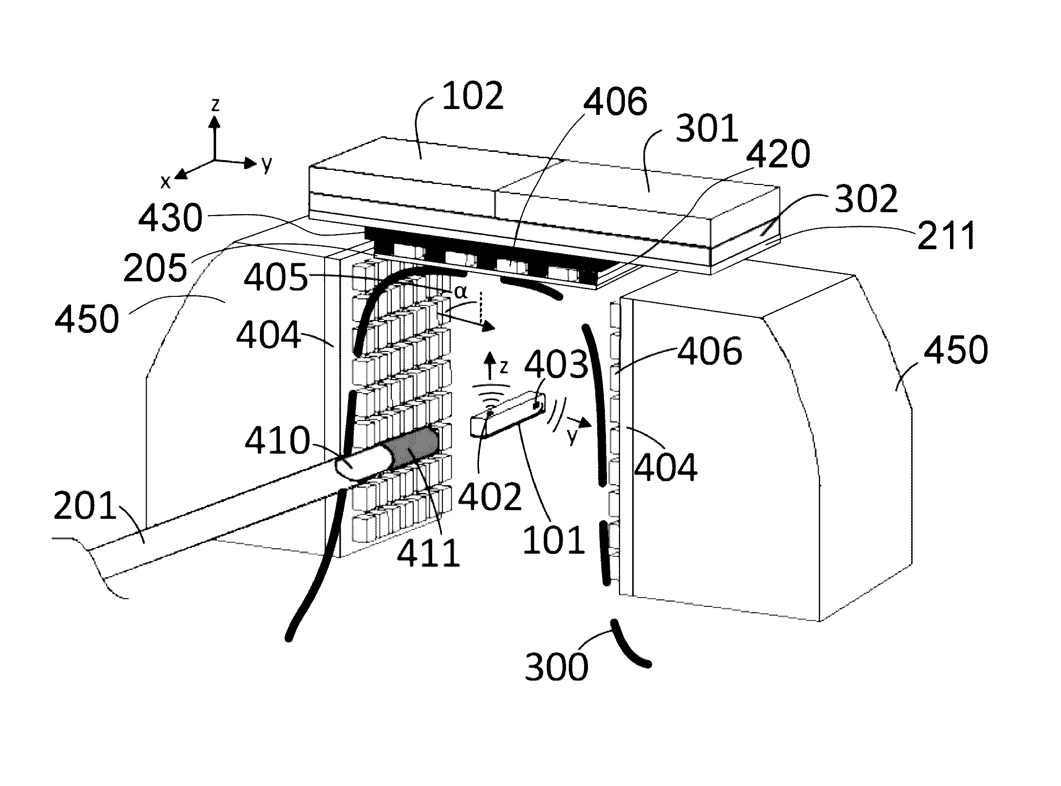
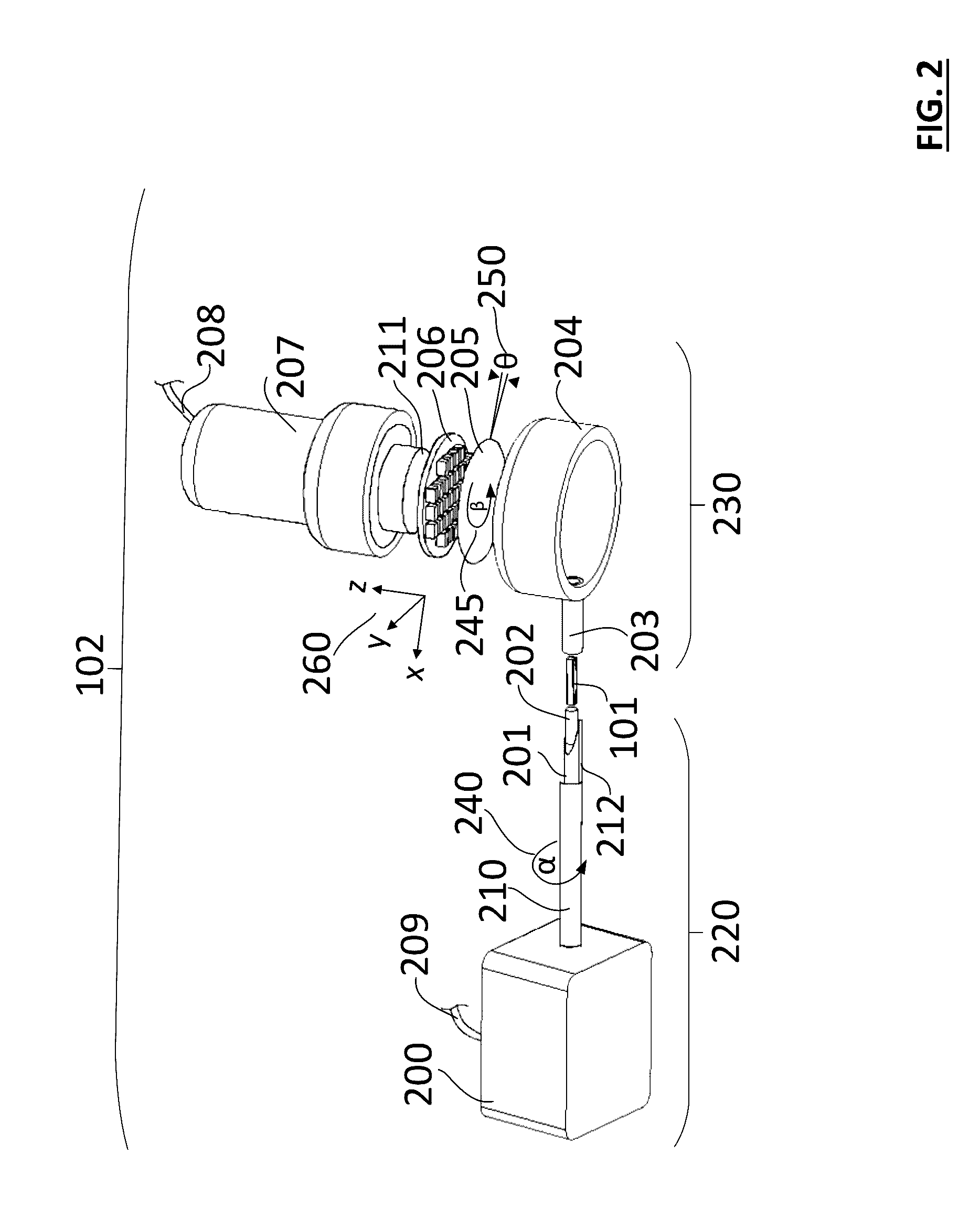
This patent describes an apparatus and method for automatically inserting and extracting a miniaturized biosensor in the body. The apparatus ensures that the biosensor is implanted in the desired position, depth, and alignment with its communication device. The method requires minimal user intervention and is pain-free. The apparatus can also locate and extract the biosensor after its useful lifetime. The invention addresses the need for proper alignment of the biosensor during the insertion process to ensure optimal function. The apparatus uses magnetic field detecting sensors and photodetectors to generate a three-dimensional mapping of the implant and automatically guide the extracting needle to the exact position of the implant. The system also enables tracking of the biosensor during and after implantation in a medium that is an obstruction to human vision. The invention satisfies the requirement that the implant and the communication device must be properly aligned to initiate operation immediately upon implantation.

Problems solved by technology

For optical wavelengths (i.e. red), if the implantation depth of the biosensor is too high, the amount of optical energy delivered is insufficient for proper operation of the biosensor.
During this injection / implantation process, two problems can arise: (i) the strong light scattering nature of the tissue can impede a trained individual (e.g. a medical doctor or nurse) to insert the biosensor in its proper location and more importantly at the proper depth underneath the skin in order for the biosensor to receive adequate amount of light; and (ii) the biosensor can rotate, which reduces the effective absorption area of its photovoltaics cells as well as misaligns its on-board LEDs.
Upon rotation, the proximity communicator is impeded from optically powering and communicating with the biosensor, which can ultimately result in the biosensing platform to be inoperable.
Biosensor extraction is typically much more challenging than insertion and requires significant more skill from a trained individual (e.g. a medical doctor or nurse) to explant it.
This stems from the fact that: (i) the miniaturized implant is difficult to be visually located or felt; (ii) the brittleness of the implant can cause it to fracture upon handling with typical tweezers, forceps, etc.
; and (iii) the surrounding tissue can grow around the implant (typically referred as fibrosis) imposing difficulties in the extraction process.

Method used


Image

  • Automated insertion and extraction of an implanted biosensor
  • Automated insertion and extraction of an implanted biosensor
  • Automated insertion and extraction of an implanted biosensor

Examples


Embodiment Construction

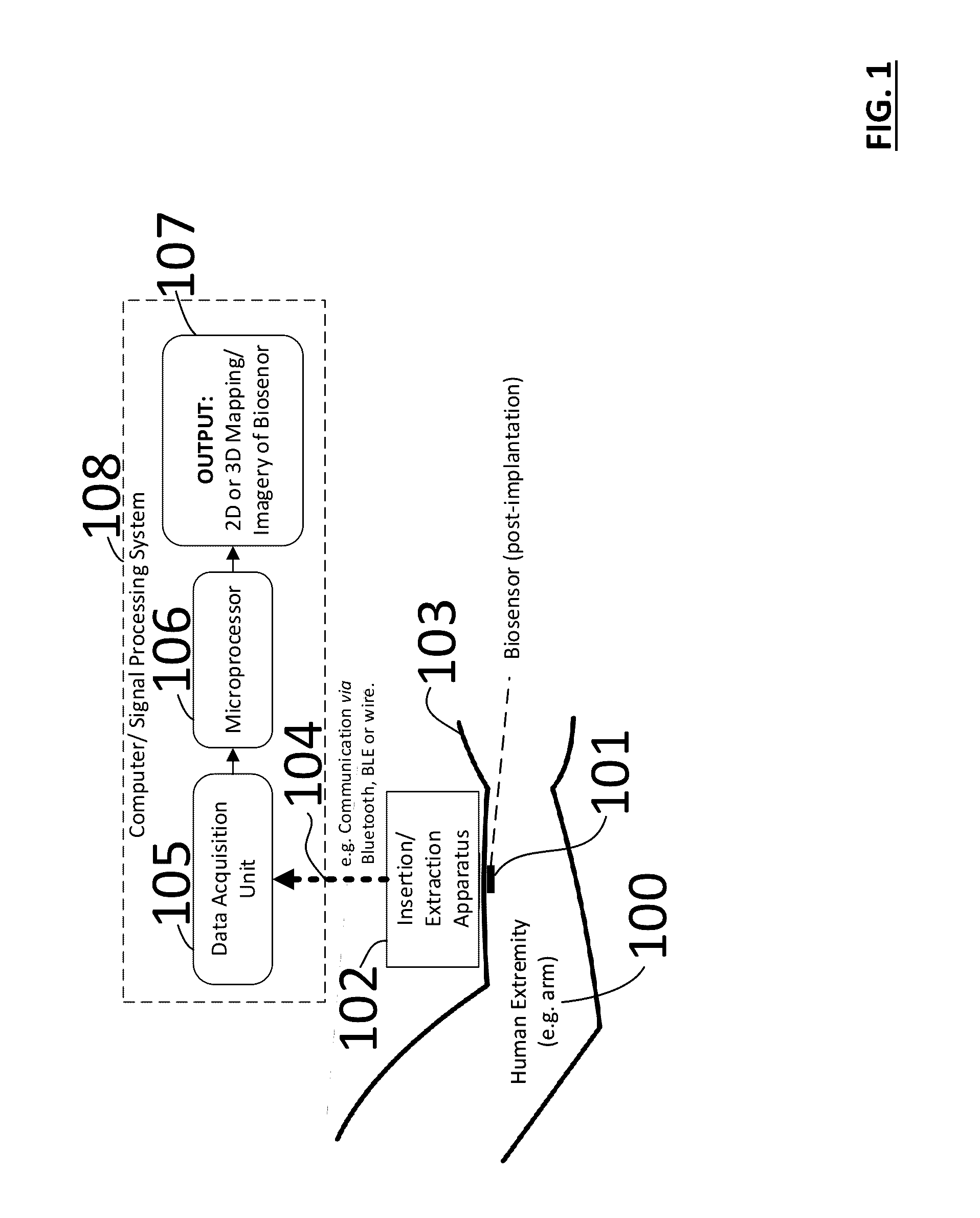
[0023]Description of the Injection / Extraction System—FIG. 1 describes the automated insertion and extraction apparatus in terms of block diagram. The insertion and extraction module 102 communicates via Bluetooth or wires 104 to a computer / signal processing system 108. The computer / signal processing system 108 further comprises from a data acquisition unit 105, a microprocessor 106 and associated computer algorithms that generate a detailed two-dimensional (2D) and three-dimensional (3D) mapping / imagery 107 of the implantable biosensor 101 with respect to the skin 103. In one example, the insertion apparatus is used to inject a miniaturized biosensor 101 into a human extremity 100 in the vicinity of the skin 103 (e.g. in the subcutaneous space). The above example is directed toward humans; however, the invention can also apply to animals and plants.

[0024]The miniaturized implantable biosensor 101 is small enough in two of its dimensions (i.e. height and width) to fit through a hypod...


PUM


Abstract

A device and method are outlined for the manual or automated insertion and extraction of a miniaturized implantable biosensor underneath the skin. System comprises injection and extraction module that is in operable communication with a positioning and tracking module, microprocessor and data acquisition units. The positioning and tracking module utilizes light- or magnetic field-sensing arrays to provide spatial (x, y) position, depth (z) and rotational (□) state of the miniaturized implant. This is fed to the injection and extraction module that lines up a catheter. For extraction, the catheter is actively guided using sensing arrays to extract the biosensor. This system has also provisions to excise fibrosis tissue around the implant. This tool is operated in a manual or automatic mode to facilitate pain-free injection and extraction of a miniaturized biosensor with minimal trauma.

Description

CROSS REFERENCE TO RELATED APPLICATIONS[0001]This application is a continuation-in-part of U.S. application Ser. No. 14 / 220,878, filed Mar. 20, 2014 and claims benefit of priority of the filing date of U.S. Provisional Application No. 62 / 239,597, filed Oct. 9, 2015, the contents of both of which are incorporated herein by referenced in their entireties.BACKGROUND OF THE INVENTION[0002]Fully implantable biosensors for use in medical applications have significant promise in diagnosing and managing human diseases. A biosensor can be defined as any device that detects a chemical or physical change, converts that signal into an electrical or chemical signal and transmits the response to a secondary device (also referred to as a proximity communicator). An implantable biosensor can be implanted within the subcutaneous tissue space as well as within the layers of skin, intramuscularly or within the vasculature. Implanting the biosensor into these locations permits the sensing of analytes (...

Claims


Application Information

Patent Timeline
Patent Type & Authority Applications(United States)
IPC IPC(8): A61B17/34A61B5/145A61M25/06A61M25/01A61M5/315A61B5/06A61B90/13
CPCA61B17/3468A61B5/062A61B5/14503A61B17/3403A61B90/13A61B2017/00039A61M5/315A61M25/0662A61B2034/2051A61B2034/2065A61B2034/2055A61M25/0127A61B5/0017A61B5/1114A61B5/14532
Inventor PAPADIMITRAKOPOULOS, FOTIOSCOSTA, ANTONIOJAIN, FAQUIRVADDIRAJU, SANTHISAGAR
Owner OPTOELECTRONICS SYST CONSULTING
Learn More