Blind spot warning device and blind spot warning system

a warning device and blind spot technology, applied in the direction of instruments, using reradiation, transportation and packaging, etc., can solve the problems of difficult adjustment of mirrors, negative aerodynamic effects, and increase the complexity of the driver interface, so as to enhance the perceptibility of the warning device, energy saving, and enhanced perceptibility

Inactive Publication Date: 2013-07-04
VOLVO TECH
View PDF10 Cites 52 Cited by
  • Summary
  • Abstract
  • Description
  • Claims
  • Application Information

AI Technical Summary

Benefits of technology

The patent text describes a warning device that can be seen at night and during the day. The device is made using materials that glow or reflect light. It can also be illuminated from the backside, which further improves its visibility. The illumination devices used are energy-efficient and relatively flat, so the device remains slim and does not become bulky. The technical effect of this invention is to provide a practical and effective solution for improving the visibility of blind spot warnings.

Problems solved by technology

The technical problem of this patent text is not specified and requires further analysis and interpretation.

Method used


Image

  • Blind spot warning device and blind spot warning system
  • Blind spot warning device and blind spot warning system
  • Blind spot warning device and blind spot warning system

Examples


Embodiment Construction

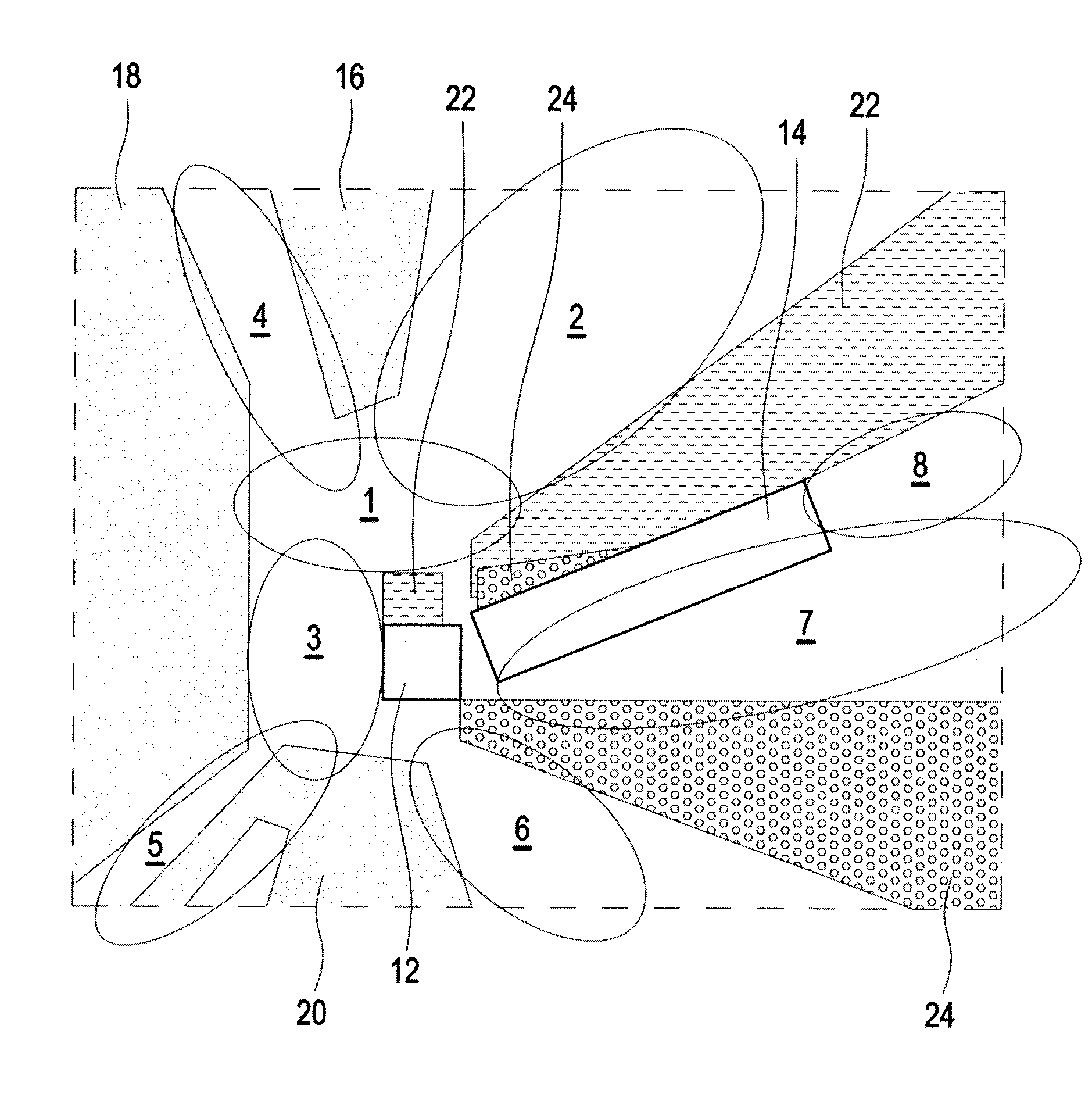
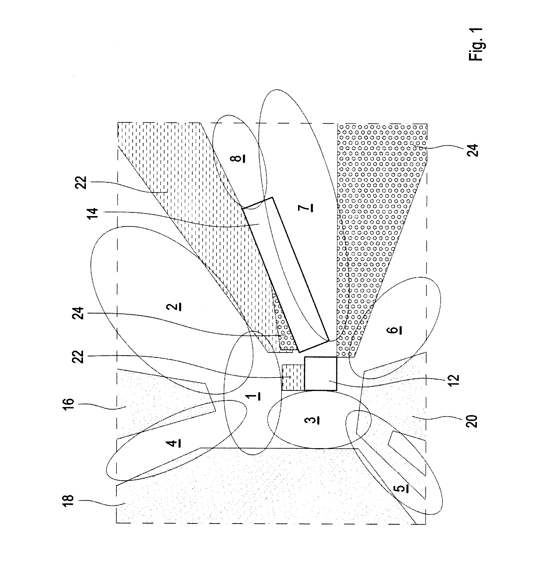
[0066]FIG. 1 shows a schematic top view of a vehicle comprising a driver's cabin 12 and a trailer 14. Usually, a driver can directly observe his environment through the windscreen and the side windows of the driver's cabin 12. Thereby, areas 16, 18 and 20 are directly visible for the driver. Indirectly through mirrors (not shown), the areas indicated by reference signs 22 and 24 are also visible for the driver. However, there remain a number of blind spot zones 1 to 8, which are not, neither directly nor indirectly, observable for the driver.

[0067]While additional mirrors can increase the driver's field of view, this solution can have negative aerodynamic effects and also increase the complexity of the driver interface. Moreover, mirrors are difficult to adjust and wide angle mirrors provide only distorted views of the surrounding traffic.

[0068]Active systems which detect and warn the driver for objects present in the blind spots may be another solution to the problem. However, this...


PUM


Abstract

A blind spot warning device is attachable to a host vehicle's exterior and includes a warning indicating at least one blind spot of the host vehicle to a target object being outside the host vehicle, wherein the warning is only perceptible for the target object in dependence on the target object's relative position to the host vehicle. Further, a blind spot detection system is disclosed, along with a vehicle including such a blind spot warning device and/or such a blind spot detection system.

Description


Claims


Application Information

Patent Timeline
Owner VOLVO TECH
Why Eureka
Try Eureka