Method for testing radio frequency interference of electromagnetic compatibility chamber

a technology of electromagnetic compatibility and radio frequency interference, which is applied in the field of electromagnetic compatibility (emc) testing technology, can solve problems such as lowering the efficiency of tests

Inactive Publication Date: 2013-07-04
HONG FU JIN PRECISION IND (SHENZHEN) CO LTD +1
View PDF4 Cites 11 Cited by
  • Summary
  • Abstract
  • Description
  • Claims
  • Application Information

AI Technical Summary

Problems solved by technology

Thereby, each antenna needs be t...

Method used


Image

  • Method for testing radio frequency interference of electromagnetic compatibility chamber
  • Method for testing radio frequency interference of electromagnetic compatibility chamber
  • Method for testing radio frequency interference of electromagnetic compatibility chamber

Examples


Embodiment Construction

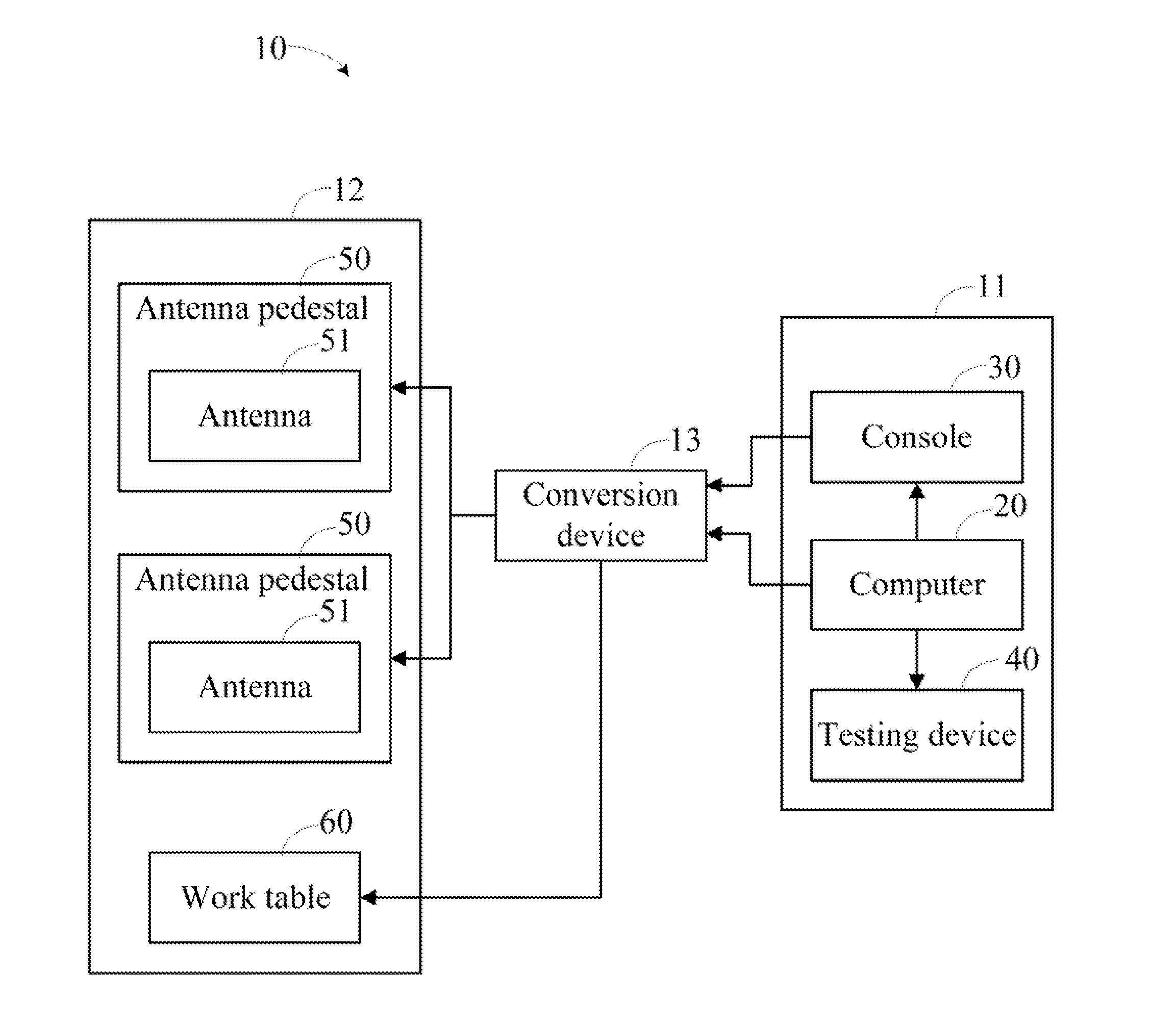
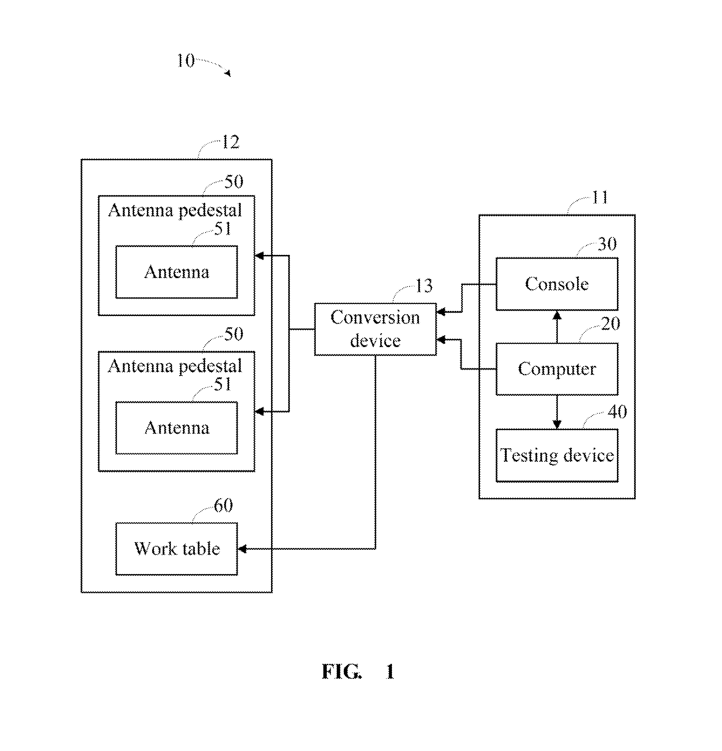
[0009]FIG. 1 is a block diagram of a testing system 10 applied in an EMC chamber. The system 10 includes an operating room 11 and an EMC chamber 12. The operating room 11 includes a computer 20, a console 30, and a testing device 40. The EMC chamber 12 includes a work table 60 and an antenna pedestal 50 configured for mounting an antenna 51. The computer 20, the console 30, and the testing device 40 are communicating with the antenna pedestal 50 and the work table 60 via a conversion device 13. The computer 20 controls height and polarization direction of the antenna pedestal 50 and rotation angle of the work table 60 by running a testing software.

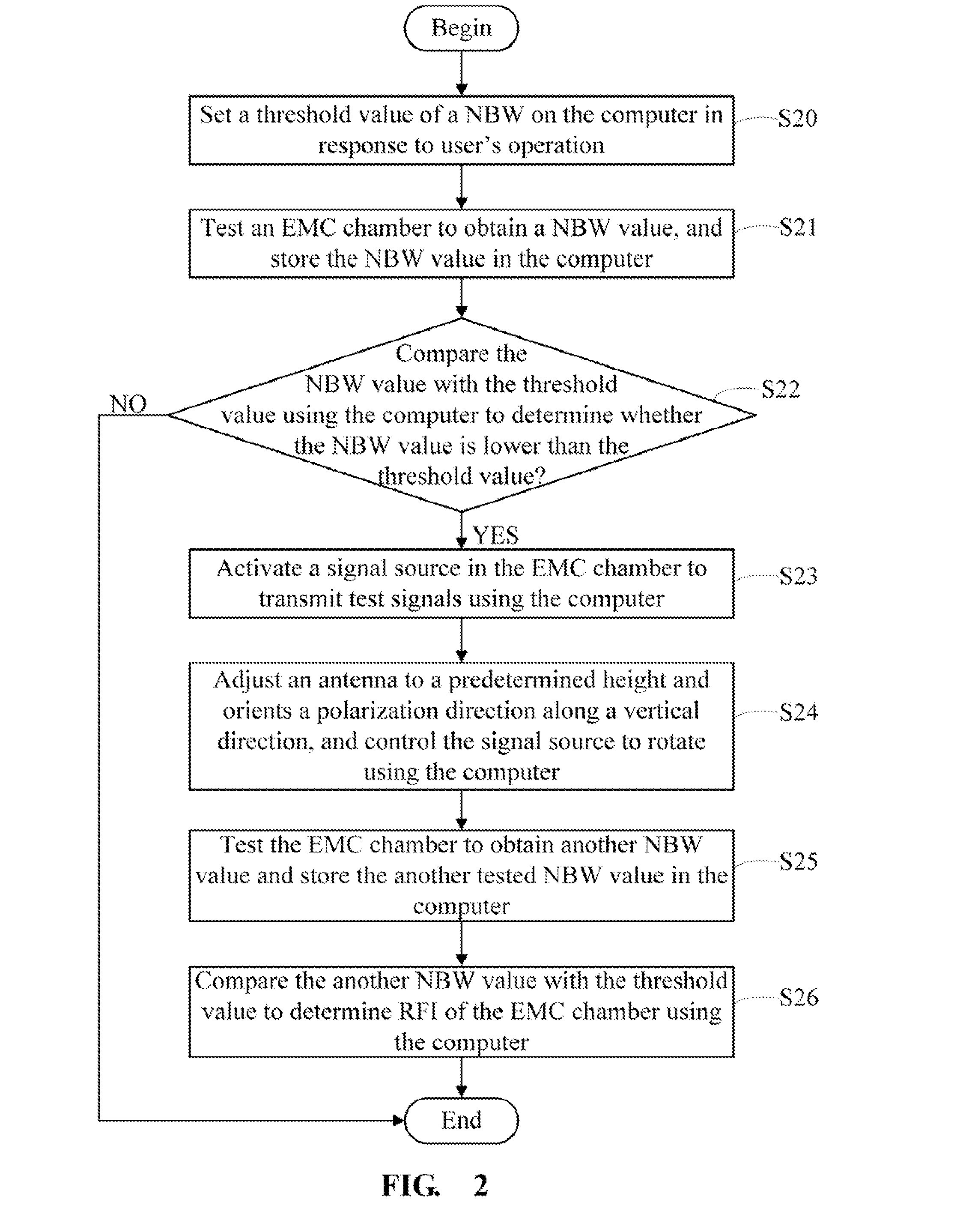
[0010]FIG. 2 is a flowchart of a method for testing RFI of the EMC chamber of FIG.1, in accordance with an exemplary embodiment.

[0011]In step S20, the computer 20 provides a user interface for operator to set a threshold value of a noise bandwidth (NBW). In the embodiment, the threshold value of NBW is about 6 dB.

[0012]In step S21, the com...


PUM


Abstract

A method for testing radio frequency interference (RFI) of electromagnetic compatibility (EMC) chamber includes: setting a threshold value of noise bandwidth (NBW) on the computer in response to user's operation, activating a signal source in the EMC chamber to transmit test signals using the computer, adjusting the antenna to a predetermined height and orients a polarization direction along a vertical direction, and controlling the signal source to rotate using the computer, testing the EMC chamber to obtain a NBW value, and comparing the NBW value with the threshold value to determine the RFI of the EMC chamber.

Description

BACKGROUND[0001]1. Technical Field[0002]The present disclosure relates to electromagnetic compatibility (EMC) testing technology, and particularly to a method for testing radio frequency interference (RFI) of the EMI chamber.[0003]2. Description of the Related Art[0004]EMC chamber configured for testing EMC of electronic devices usually employs two antennas. Generally, when testing EMC in the EMC chamber, parameters of each of the two antennas should be respectively tested in vertical polarization direction and horizontal polarization direction using a signal source. Thereby, each antenna needs be tested twice, lowering tests efficiency.[0005]Therefore, there is room for improvement within the art.BRIEF DESCRIPTION OF THE DRAWINGS[0006]The components in the drawings are not necessarily drawn to scale, the emphasis instead being placed upon clearly illustrating the principles of the disclosure. Moreover, in the drawings, like reference numerals designate corresponding parts throughou...

Claims


Application Information

Patent Timeline
IPC IPC(8): H04B17/00
CPCG01R29/0814G01R35/00H04B17/345G01R31/001G01R29/0821
Inventor YANG, YONG-SHENG
Owner HONG FU JIN PRECISION IND (SHENZHEN) CO LTD
Why Eureka
Try Eureka