Display device

a display device and display technology, applied in the field of directviewing display devices, can solve the problems of slow rate, image quality degradation, and difficulty in immediately providing display devices with the larger area

Active Publication Date: 2013-07-11
SHARP KK
View PDF7 Cites 31 Cited by
  • Summary
  • Abstract
  • Description
  • Claims
  • Application Information

AI Technical Summary

Benefits of technology

[0035]According to the present invention, a direct-viewing type display device with obscured joints is provided.

Problems solved by technology

Representative examples of large-sized display devices are display devices in which self-light-emitting elements such as light-emitting diodes (LEDs) are arranged in a matrix array and projection display devices; however, these have disadvantages in terms of image quality.
The substrates that are available for mass production will become more increased in size, however at a slow rate.
It is difficult to immediately provide display devices with the larger areas that are required on the current market.
However, the tiling technique induces a problem of visible joints between the plurality of display devices.

Method used


Image

  • Display device
  • Display device
  • Display device

Examples


first embodiment

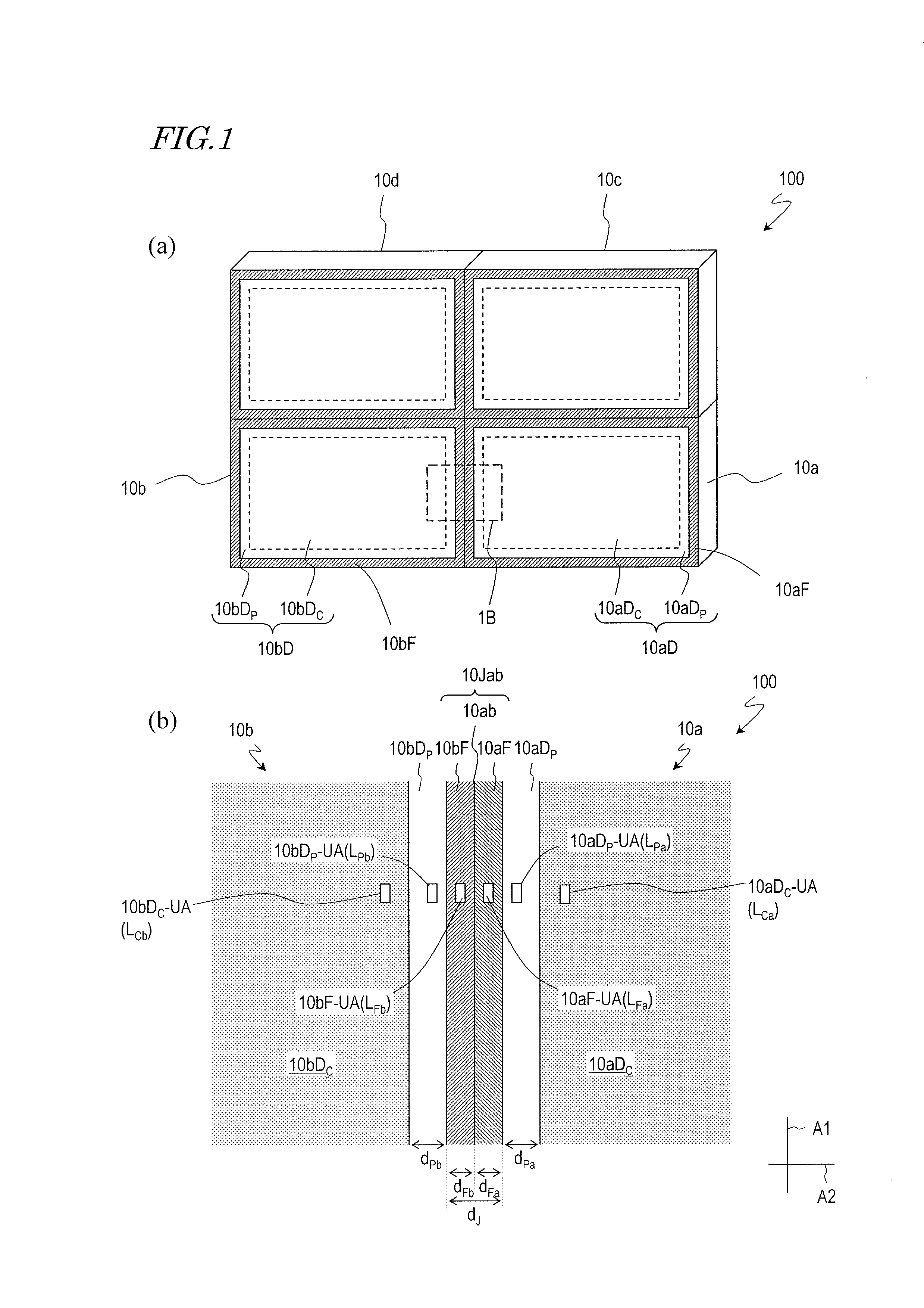
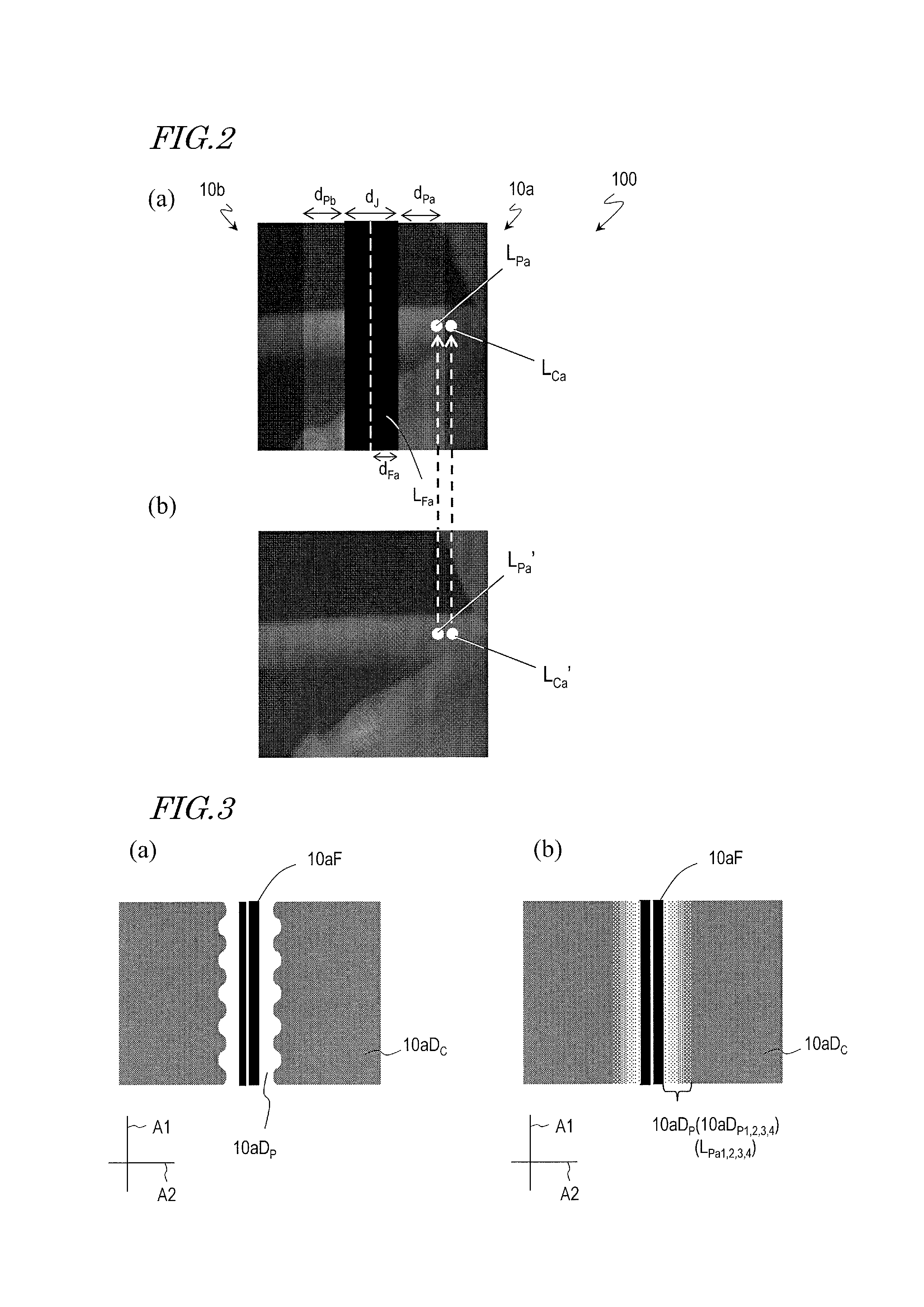
[0048]First, with reference to FIG. 1 to FIG. 4, the structure of a liquid crystal display device 100 according to the present invention as well as the operation thereof will be described.

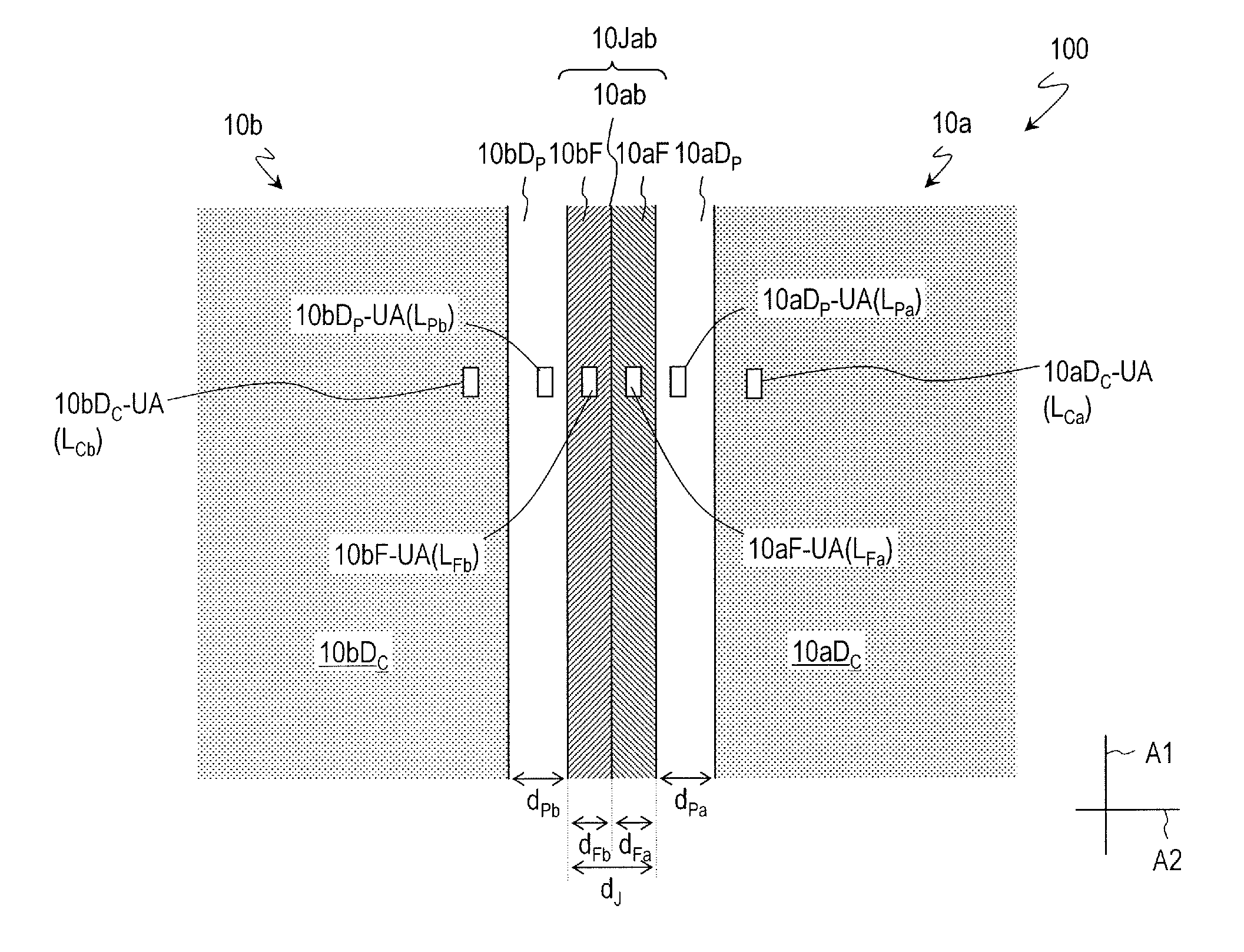
[0049]As shown in FIG. 1(a), the liquid crystal display device 100 includes liquid crystal display panels 10a to 10d, which compose matrix tiling. It will be appreciated that there is no limit to the number of liquid crystal display panels to be included in the liquid crystal display device according to an embodiment of the present invention, and there is no limit to the manner in which they are arrayed. The liquid crystal display panels 10a to 10d, which are disposed so that their respective frame regions are adjacent to one another, are linked together with an adhesive or the like. Herein, the portion composed of an adhesive or the like will be referred to as the linking portion (the linking portion 10ab in FIG. 1(b)).

[0050]In the following, the structure of the liquid crystal display panels 10a ...

second embodiment

[0071]Next, with reference to FIG. 5 and FIG. 6, the fundamental structure of a liquid crystal display device 200 according to the present invention as well as the operation thereof will be described.

[0072]The liquid crystal display device 200 includes: a display panel 20a having a display region 20aD and a frame region 20aF, the frame region 20aF being formed outside the display region 20aD and extending along the first axis A1; a display panel 20bD having a display region 20bD and a frame region 20bF, the frame region 20bF being formed outside the display region 20bD and extending along the first axis A1; a linking portion 20ab which links together the frame region 20aF of the display panel 20a and the frame region 20bF of the display panel 20b; and a joint region 20Jab, which includes the frame region 20aF and the frame region 20bF. The liquid crystal display device 200 further includes a plurality of light sources 42a which are provided in the frame region 20aF. Although an exam...


PUM


Abstract

A direct-viewing type display device (100) includes: first and second display panels (10a, 20a); and a joint region (10Jab) containing a linking portion (10ab) which links together the first frame region (10aF) and the second frame region (10bF) and containing the first and second frame regions (10aF, 10bF). The first display region (10aD) of the first display panel (10a) has a first peripheral display region (10aDPa) which adjoins the first frame region (10aF) and a first middle display region (10aDC) which adjoins the first peripheral display region (10aDPa). Each region has a plurality of unit-regions, and an average luminance LPa of a plurality of first peripheral unit-display regions (10aDPa-UA) contained in the first peripheral display region (10aDPa) is higher than an average luminance LCa of a plurality of first middle unit-display regions (10aDC-UA) contained in the first middle display region (10aDC).

Description

TECHNICAL FIELD[0001]The present invention relates to a display device, and more particularly to a direct-viewing type display device.BACKGROUND ART[0002]In recent years, there is a strong desire for an increase in the size of television sets and display devices for displaying information. Representative examples of large-sized display devices are display devices in which self-light-emitting elements such as light-emitting diodes (LEDs) are arranged in a matrix array and projection display devices; however, these have disadvantages in terms of image quality. Therefore, a further increase in the size of direct-viewing type liquid crystal display devices (LCDs) and plasma display devices (PDPs), which are capable of displaying with a high image quality, is being desired.[0003]Since a direct-viewing type liquid crystal display device or a plasma display device is basically formed on a glass substrate, its screen size depends on the substrate size. Currently, the largest of glass substr...

Claims


Application Information

Patent Timeline
Patent Type & Authority Applications(United States)
IPC IPC(8): G09G3/34H05K7/02
CPCG02F1/1333G09F9/00G09F9/40G09G3/34G02F2201/44G09G2310/0232G02F1/13336G09G2300/026H05K7/026
Inventor WATANABE, HISASHIOKAMOTO, KENJI
Owner SHARP KK
Why Eureka
Try Eureka