Velocity Measuring System

a velocity measurement and speed technology, applied in the field of velocity measurement system, can solve problems such as inaccurateness of techniques, and achieve the effects of reducing laser coherence length, preventing mode-hop instabilities, and avoiding undesirable laser mode-hop instabilities

Active Publication Date: 2013-08-22
TELEDYNE
View PDF1 Cites 6 Cited by
  • Summary
  • Abstract
  • Description
  • Claims
  • Application Information

AI Technical Summary

Benefits of technology

The patent describes a new device that can measure the direction and flow rate of liquid in an open channel flow with very high precision. To avoid long periods of laser instability, the device only powers up the laser for short periods of time, and collects data during these periods. The device can use a small heater to keep the laser at a stable temperature and to improve power efficiency. Overall, the device is designed to increase accuracy and efficiency in measuring liquid flow in open channels.

Problems solved by technology

This technique has the disadvantages of being inaccurate under some circumstances due to the difficulty in accurately arriving at the mean flow velocity from the surface velocity, and of detecting a signal when there are few suitable reflectors on the surface.

Method used


Image

  • Velocity Measuring System
  • Velocity Measuring System
  • Velocity Measuring System

Examples


Embodiment Construction

[0068]Reference will now be made in detail to the subject matter disclosed, which is illustrated in the accompanying drawings.

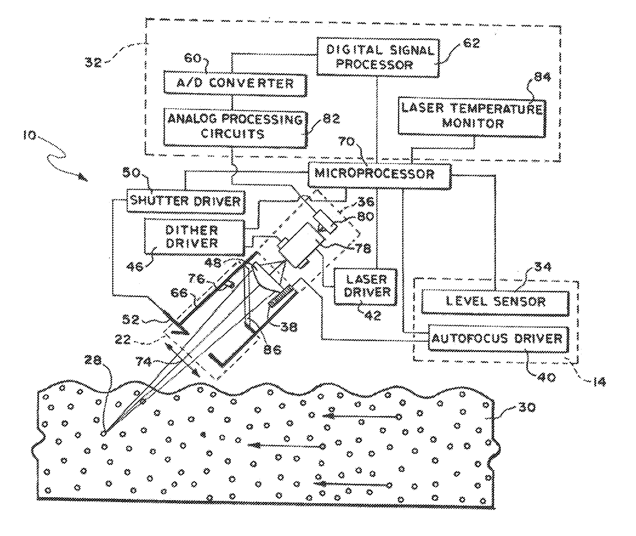
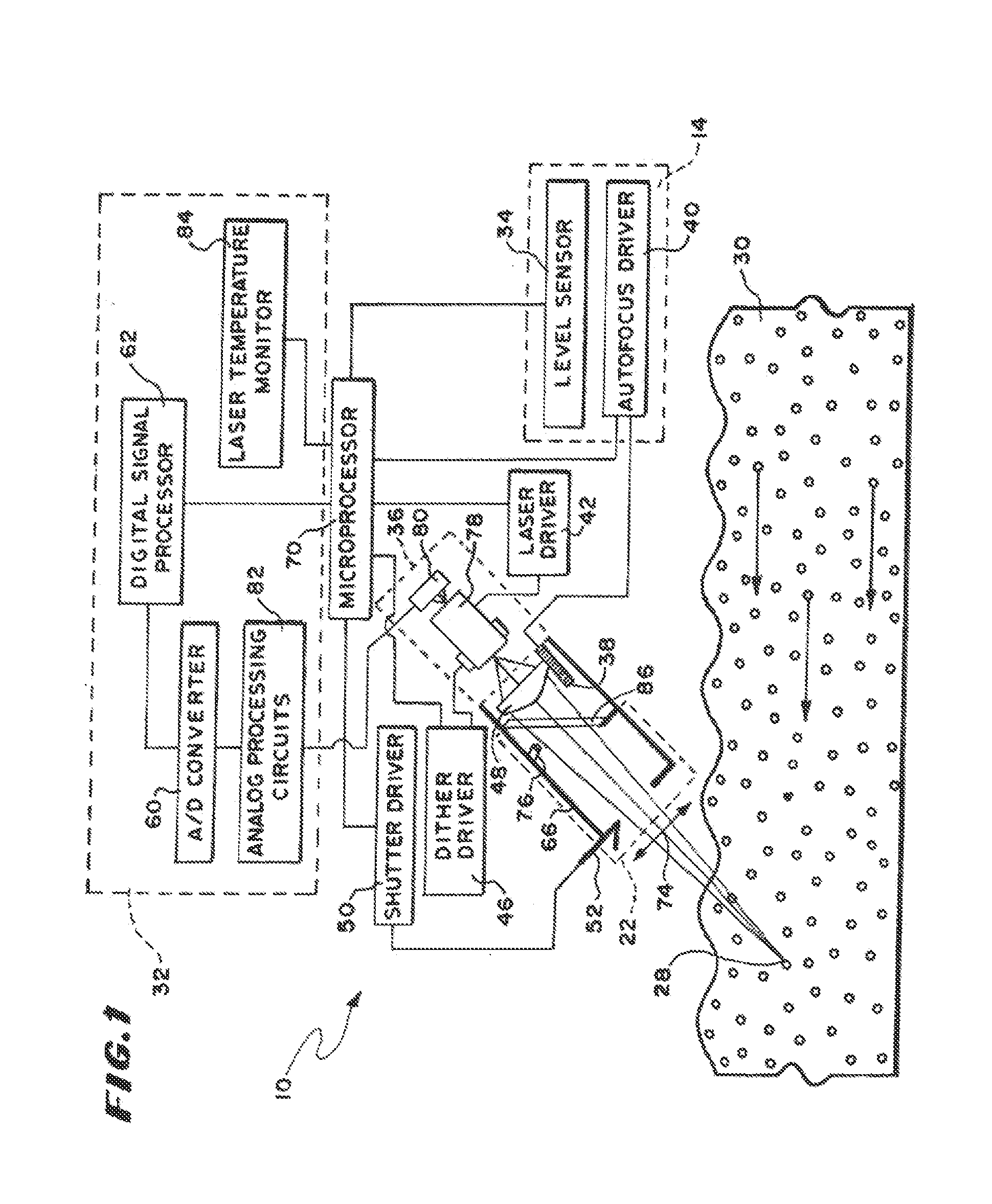
[0069]In FIG. 1, is shown a schematic block diagram of a flow meter for remotely measuring the average velocity of an open channel flow, 30. In this specification the words “open channel flow”, “flow”, “liquid flow”, “rate of flow” and “flowing steam” are used from time to time to designate the medium for which the flow meter is used. These words are not intended to be words of limitation as to the nature of the liquid, the rate of which is being measured, and the novel flow meter and are interchangeable when designating the medium characteristics of which are being measured. The flow meter 10 includes as its principal parts a Doppler beat frequency subsystem 32, a laser diode module 36, a microprocessor subsystem and input / output devices 70, a laser temperature and flow stream level monitoring system 14, and a environmental protection system 22. The flow met...


PUM

PropertyMeasurementUnit
Brewster's angleaaaaaaaaaa
beat frequencyaaaaaaaaaa
frequencyaaaaaaaaaa

Abstract

A laser Doppler velocimeter uses self-mixing amplification of backreflections from scatterers below the surface of a flow. A time domain signal is divided into segments that are roughly equal to a transit time of particles through a focus of a laser beam. The segments are connected to a frequency domain through the use of an FFT algorithm to produce frequency domain data segments. Signal-to-noise ratio is enhanced through signal processing techniques using the segments to produce a final enhanced signal spectrum.

Description

CROSS REFERENCE TO RELATED APPLICATIONS[0001]The present application claims priority the benefit under 35 U.S.C. §120 to U.S. application Ser. No. 12 / 800,750 filed May 21, 2010. Said U.S. application Ser. No. 12 / 800,750 is hereby incorporated by reference in its entirety.BACKGROUND OF THE INVENTION[0002]This invention relates to methods and apparatuses for measuring the average velocity of an open channel flow using electromagnetic radiation such as, for example, laser signals to determine velocity by Doppler shift techniques without physically contacting the flow but measuring the flow below the surface.[0003]In one class of Doppler shift remote sensing of the velocity of an open channel flow, a laser beam is transmitted to a flow from above and the backscatter received from scatterers in the fluid such as bubbles, solid objects (e.g. debris) or microscopic particles (e.g. colloid) causing turbidity, carried by the flow are sensed. The Doppler shift in frequency between the transmi...

Claims


Application Information

Patent Timeline
Patent Type & Authority Applications(United States)
IPC IPC(8): G01P5/26
CPCG01P5/26G01S7/4812G01S7/4916G01S2007/4977G01S7/497G01S17/58G01S7/493
Inventor CHRISTIAN, WILLIAM R.DELCHER, RAY C.CHEN, TONGKHOSHNEVISAN, MOHSENLIESCHESKI, PHILLIP B.METCALF, MICHAEL A.
Owner TELEDYNE
Why Eureka
Try Eureka