Eureka AIR delivers breakthrough ideas for toughest innovation challenges, trusted by R&D personnel around the world.

Magnetism metric controller

a metric controller and magnetism technology, applied in the field of magnetism controllers, can solve the problems of high-speed and precise scrolling, easy inconsistent control of design on grating theories, and improve the resolution of the design. the effect of precision and resolution

Inactive Publication Date: 2007-04-24
UC LOGIC TECH CORP +1
View PDF2 Cites 7 Cited by
  • Summary
  • Abstract
  • Description
  • Claims
  • Application Information

AI Technical Summary

Benefits of technology

The present invention provides a magnetism metric controller that offers higher precision and resolution compared to prior art. It uses a magnetic field sensor to control the rotation of a shaft or the position of a moving part. The magnetic field sensor is a permanent magnet that generates a consistent and reliable signal, even in the presence of external noise. The control sensitivity can be adjusted via a microprocessor, and the size of the controller can be reduced for smaller indicators. The use of a permanent magnet and Hall sensor simplifies the design and reduces production costs. The invention can be adapted for any information product that requires metric control. Overall, the present invention provides a more accurate and efficient solution for controlling rotation and position.

Problems solved by technology

1. Shorter service life. The scrolling metric control relates to mechanical movement since the achievement of scrolling metric control of the prior art relies upon a switch encoder.
Though the grating sensor is used for the rotation metric control of the latest indicator for longer service and more comfortable operation feel; the design on grating theories is vulnerable to inconsistent control.
The design on grating theories for the rotation metric control of the latest indicator fails to improve its resolution, thus to prevent high-speed and precise scrolling.
Larger space consumed by the grating sensor device and its structure frustrates the application in the smaller indicator.
5. Higher production cost.
Whereas the grating device dominates the primary control in the rotation metric control of the latest indicator, its assembly is comparatively complicated to increase the cost of the device, and the time and efforts needed for assembly.

Method used


Image

  • Magnetism metric controller
  • Magnetism metric controller
  • Magnetism metric controller

Examples


Embodiment Construction

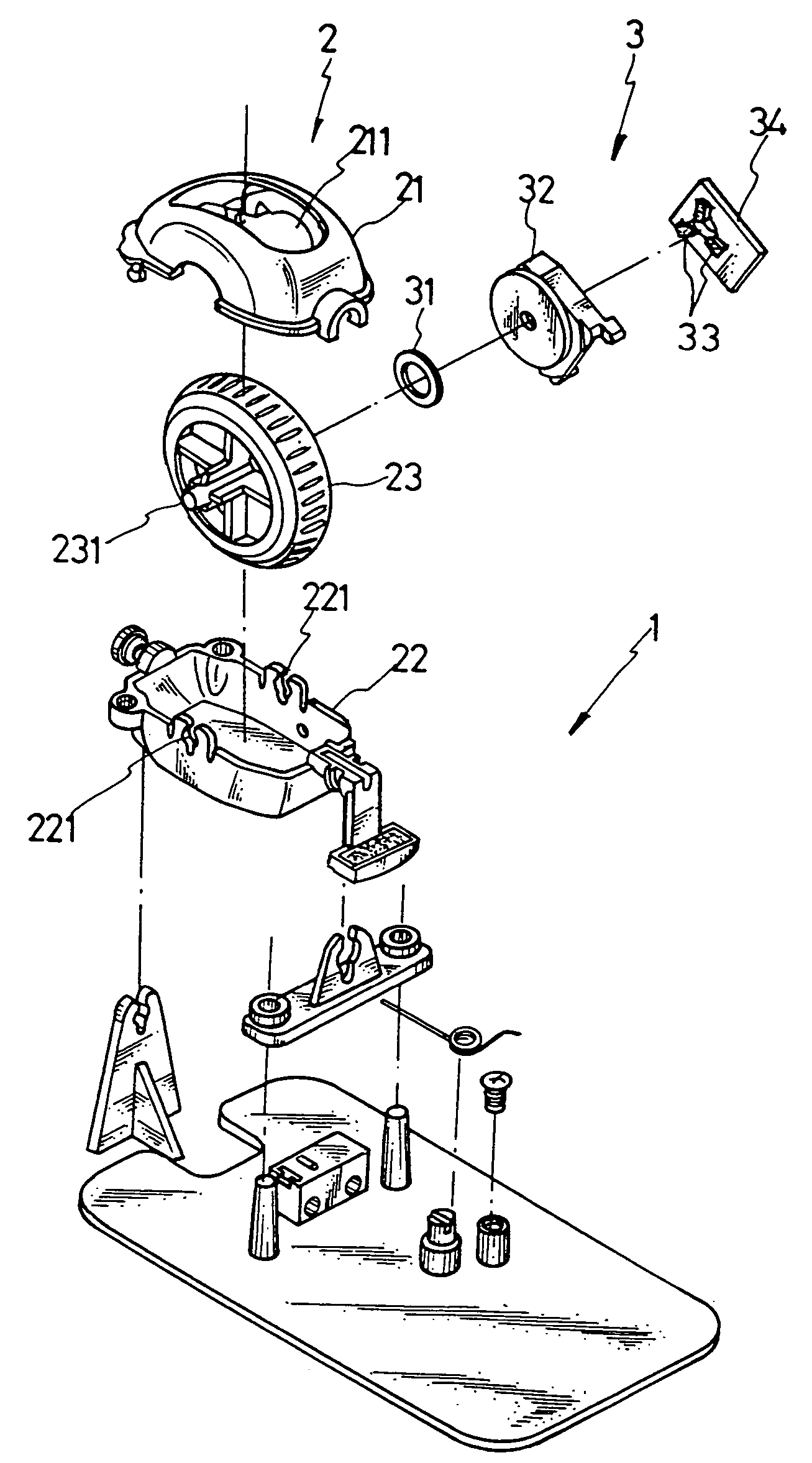
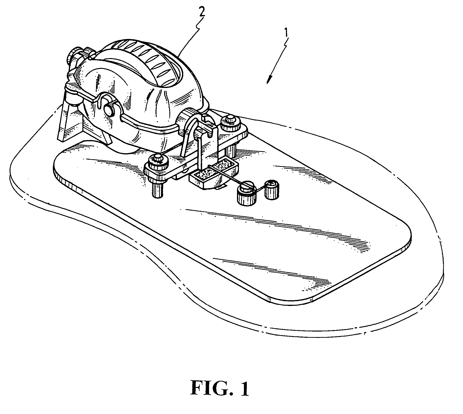
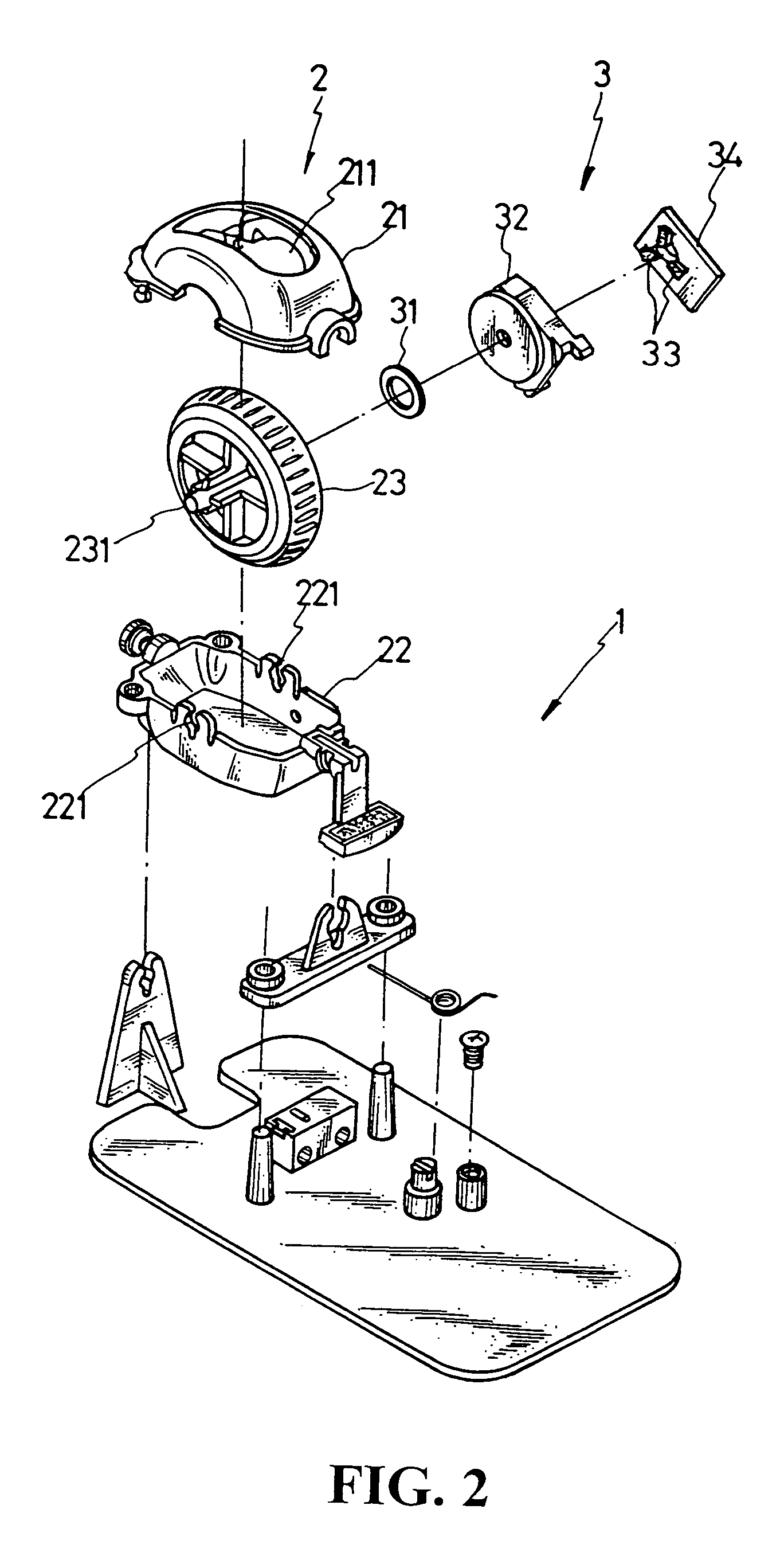
[0026]The following descriptions are of exemplary embodiments only, and are not intended to limit the scope, applicability or configuration of the invention in any way. Rather, the following description provides a convenient illustration for implementing exemplary embodiments of the invention. Various changes to the described embodiments may be made in the function and arrangement of the elements described without departing from the scope of the invention as set forth in the appended claims. Referring to FIG. 1, the present invention is essentially comprised of a scrolling wheel mechanism (2); therefore, there is no need to put any limitation on the target object of its application. As illustrated in FIG. 2, the present invention is essentially comprised of the scrolling wheel mechanism (2) and a signal retrieval installation (3). The scrolling wheel mechanism (2) includes (21), a pivot holder (22), and a scrolling wheel (23); and the signal retrieval installation disposed at where ...


PUM


Abstract

A precise, consistent, reliable, and high resolution magnetism metric controller applied in electronic and information devices is comprised of a scrolling wheel mechanism to drive by rotation a permanent magnet to retrieve signals of changed magnetic field due to displacement of magnetic poles of the permanent magnet.

Description

BACKGROUND OF THE INVENTION[0001](a) Technical Field of the Invention[0002]The present invention is related to a magnetism controller, and more particularly, to one retrieves signals of changed magnetic filed created by displacement of a permanent magnet driven by rotation.[0003](b) Description of the Prior Art[0004]Many peripherals including keyboard, mechanical roller mouse and up to present optical mouse or wireless mouse for the control and movement of cursor on screen in computer system have been consecutively introduced with their primary purposes of include cursor movement control, page scrolling and click control.[0005]Whereas users were not satisfied with the slow and inconvenient use of the keyboard at the beginning in providing functions of an indicator, the mouse was invented. Up to now, mouse remains the most favored indicator to computer users. However, indicators either in earlier or current types are found with many limitations and defectives, such as:[0006]1. Shorte...

Claims


Application Information

Patent Timeline
Patent Type & Authority Patents(United States)
IPC IPC(8): G01B7/30G09G5/08
CPCG06F3/0362
Inventor LEE, WEN-CHINCHEN, SHANG-HAO
Owner UC LOGIC TECH CORP
Why Eureka
Eureka Blog
Learn More