
Lighting Apparatus and Method of Skull Lighting

a lighting apparatus and skull technology, applied in the field of lighting apparatus and method of lighting, can solve the problems of difficult lighting of three-dimensional cavernous structures for ornamental purposes, damage or deterioration of the interior of the structure, and visual difficulty in distinguishing the features of the skull

Inactive Publication Date: 2013-08-22
OLD GOAT OUTDOORS
View PDF3 Cites 8 Cited by
  • Summary
  • Abstract
  • Description
  • Claims
  • Application Information

AI Technical Summary

Benefits of technology

The invention is about a lighting system that can light up the inside of a cavernous structure without damaging or negatively affecting it. The system uses a method called European mounting, which allows for the safe and secure display of objects using LED lights. This technology provides lighting without the risk of burning or damaging the objects. The technical effect of this patent is the ability to provide sufficient lighting for display purposes without causing any harm to the environment or the objects being displayed.

Problems solved by technology

Three-dimensional cavernous structures can be difficult to light for ornamental purposes.
Such structures typically need to be lit from the inside, but if the light source is too close to the material of the structure, the light may run too hot thereby damaging or deteriorating the interior of the structure.
Another problem with lighting three-dimensional cavernous structures is finding a light source that is capable of evenly distributing the light so that the entire structure is well-illuminated, rather than one intense light source that does not allow for adequate observation of a structure's ornate detail.
Although the bleached skull is white, after it has been mounted it may appear dark, and it is visually difficult to distinguish the features of the skull.
Indeed, in dimly or darkly lit areas the mounted skull may not appear very attractive.
Presently, there are no effective ways to improve the appearance of a mounted skull.

Method used


Image

  • Lighting Apparatus and Method of Skull Lighting
  • Lighting Apparatus and Method of Skull Lighting
  • Lighting Apparatus and Method of Skull Lighting

Examples


Embodiment Construction

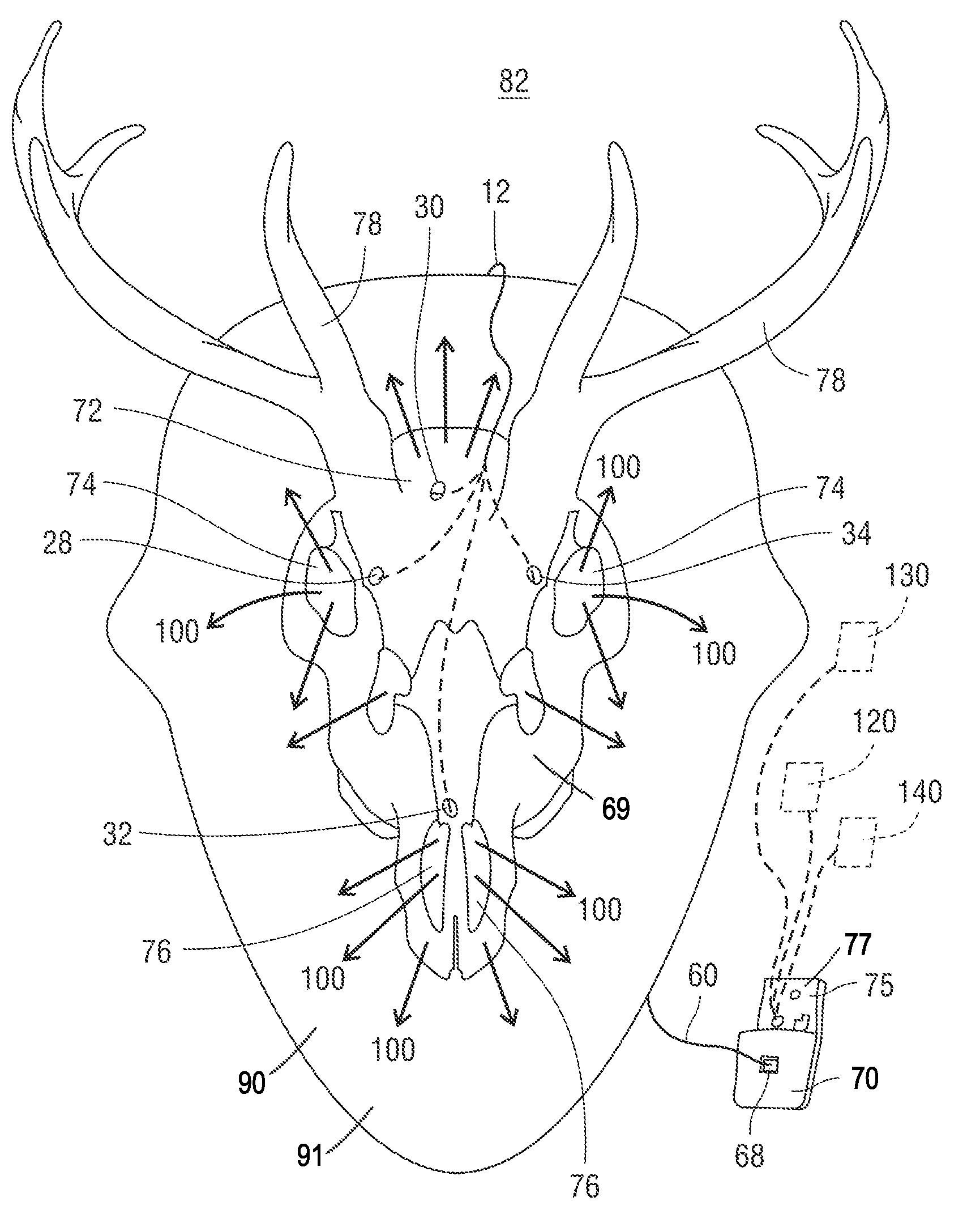
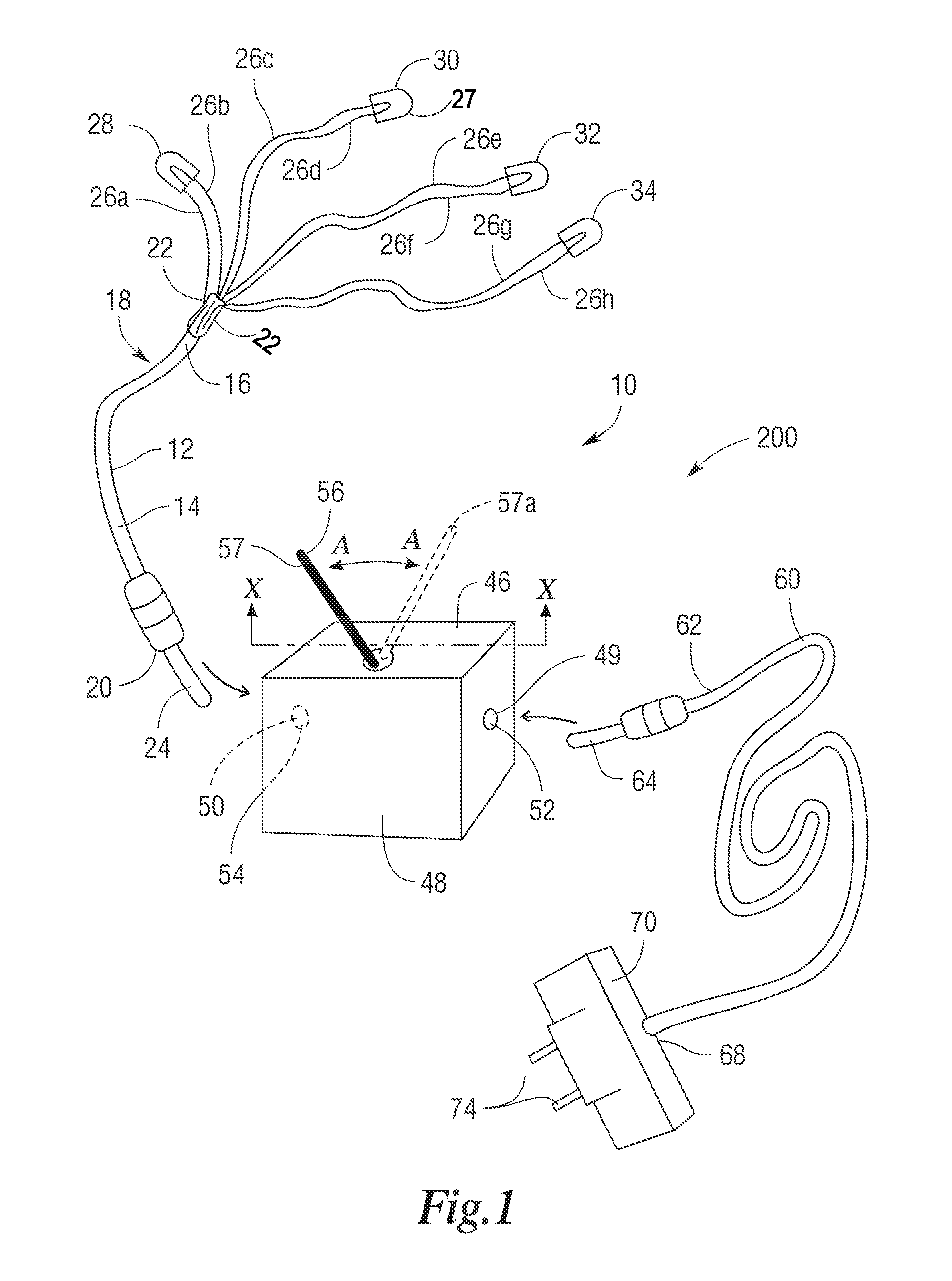
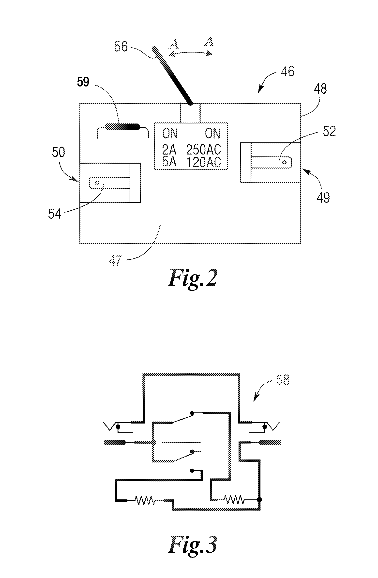
[0023]Turning now to FIG. 1, shown therein are the components of the lighting apparatus 10. The lighting apparatus 10 includes a lighting harness 12 that includes a harness power cord 14. The harness power cord 14 has an outer casing 16 that provides for insulation, and disposed internal to the outer casing 16 are a plurality of electrical leads 18. In one of the preferred embodiments the plurality of electrical leads 18 are in the form of pairs of first, second, third and fourth electric leads 26a, 26b, 26c, 26d, 26e, 26f, 26g, 26h. The harness power cord 14 also has opposed first and second harness power cord ends 20, 22. The first power cord end 20 has attached to it an electric socket 24. The second end 22 of the harness power cord 14 is joined to a wire guide component 22a. As shown, the pairs of first, second, third and fourth electric leads 26a, 26b, 26c, 26d, 26e, 26f, 26g, 26h extend through the wire guide component 22a such that they are disposed outside the outer casing 1...


PUM

PropertyMeasurementUnit
Poweraaaaaaaaaa
Shapeaaaaaaaaaa

Abstract

A lighting apparatus is provided that includes a lighting harness having a harness power cord. Disposed internal to the harness power cord are pairs of electrical leads for providing electrical power to LED's. The harness power cord is plugged into a switch. There is also a power source cord having a first power cord source end that is plugged into the switch and the power source cord has a second power cord source end that is connected to a transformer. The transformer is capable of being plugged into a wall receptacle. The lighting harness is disposed internal to the skull of an animal such that the LED's are capable of illuminating the skull when supplied with electric power via the lighting harness.

Description

CROSS-REFERENCE TO RELATED APPLICATIONS[0001]This application claims the benefit of U.S. Provisional Application No. 61 / 601,914, filed Feb. 22, 2012, and claims the benefit of U.S. Provisional Application No. 61 / 696,371, filed Sep. 4, 2012, the disclosures of which are incorporated herein by reference.FIELD OF INVENTION[0002]This invention is directed to a lighting apparatus and method of lighting particularly suitable for lighting the interior of a three-dimensional cavernous structure.BACKGROUND OF INVENTION[0003]Three-dimensional cavernous structures can be difficult to light for ornamental purposes. Examples of three-dimensional cavernous structures can include sculptures and animal skulls, either of which may be translucent. Such structures typically need to be lit from the inside, but if the light source is too close to the material of the structure, the light may run too hot thereby damaging or deteriorating the interior of the structure. As a result, in some instances, the d...

Claims


Application Information

Patent Timeline
IPC IPC(8): F21V33/00H01R43/26
CPCF21V33/0028H01R43/26B44C5/02Y10T29/49117F21V23/04F21Y2101/02F21S4/001F21S4/10F21Y2115/10
Inventor CARROLL, MICHAEL E.
Owner OLD GOAT OUTDOORS
Learn More