Heating device for conductive heating of a sheet metal blank

a heating device and conductive technology, applied in the direction of heating elements, shaping tools, electrical devices, etc., can solve the problems of high production cost, corresponding burden on the environment due to consumed energy, heat input into the sheet metal blank, etc., to reduce production costs, increase mass, and increase mass

Inactive Publication Date: 2015-10-01
BENTELER AUTOMOBILTECHNIK GMBH
View PDF5 Cites 7 Cited by
  • Summary
  • Abstract
  • Description
  • Claims
  • Application Information

AI Technical Summary

Benefits of technology

[0014]A further significant advantage of the invention is that when the compensation element is contacted with corresponding electrodes, in particular the contact regions or reception regions for the electrodes on the compensation element are configured with a high mass or are relatively thick. This results in a small current flux density in this region, thus resulting in only minor heating on the compensation element. Consequently no separate cooling is required in the region of the connection of the electrodes even in the case of high-load heating with the corresponding compensation element according to the invention.
[0015]The heating device according to the invention can in particular be integrated into a production line for producing hot formed and press hardened or heat treated sheet metal components, preferably steel sheet components, wherein heating can be achieved within a very short time, in particular within the production cycle. For this the heating device is preferably fastened on an industrial robot so that the heating device can be used as a manipulator or transport device. In particular a heating device is used for this purpose in order to take up the sheet metal blank from a stack or a conveyor and to transport it to a further processing device, in particular a hot forming press, while simultaneously heating during the transport.
[0016]Within the framework of the invention a further positive effect is that the compensation element generally has a greater mass relative to the metal blank, which is also heated. The compensation element then at least partially gives off heat energy contained in it by thermal conduction to the sheet metal plate, which reduces production costs compared to the purely conductive resistance heating. By targeted selection of the cross sectional surface of the hot compensation element, i.e., the compensation element used during the production, it is thus possible to achieve an optimum between heat conduction and conductive heating due to current flow through the sheet metal blank itself.
[0017]According to another advantageous feature of the invention the compensation element contacts the surface of the sheet metal blank with its entire surface. In order to improve a full surface contact, the contact surface of the compensation element is in particular configured concave toward the sheet metal blank. It thus has an inward bulge toward the compensation element. The sheet metal blank is thus pulled toward the contact surface.
[0018]As an alternative or in addition further a corresponding press force can be exerted via the compensation element, so that a gap between the contact surfaces of the compensation element and the blank is reduced to zero thus resulting in an almost complete contact. Further particularly preferably the compensation element is a part of a pressing tool or a temperature treatment station so that the plate is inserted into the temperature treatment station and then a corresponding pressing force is exerted.
[0019]For further enhancing the full surface contact, according to the invention under-pressure channels are provided in the compensation element so that when applying an underpressure on the underpressure channels a suction effect is created for pulling the sheet metal blank to the compensation element.

Problems solved by technology

This means high production costs and also a corresponding burden on the environment due the consumed energy.
Applying a current thus results in a heat input into the sheet metal blank.

Method used


Image

  • Heating device for conductive heating of a sheet metal blank
  • Heating device for conductive heating of a sheet metal blank
  • Heating device for conductive heating of a sheet metal blank

Examples


Embodiment Construction

[0039]Throughout all the Figures, same or corresponding elements are generally indicated by same reference numerals. These depicted embodiments are to be understood as illustrative of the invention and not as limiting in any way. It should also be understood that the drawings are not necessarily to scale and that the embodiments are sometimes illustrated by graphic symbols, phantom lines, diagrammatic representations and fragmentary views. In certain instances, details which are not necessary for an understanding of the present invention or which render other details difficult to perceive may have been omitted.

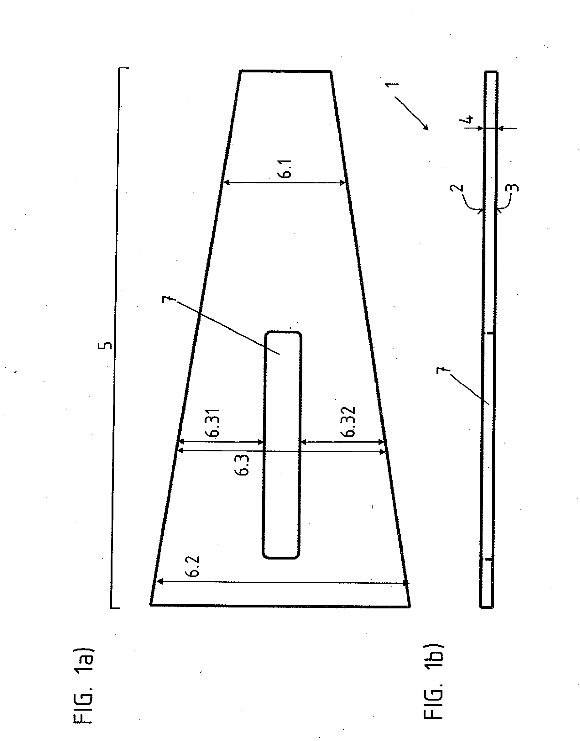
[0040]Turning now to the drawing, and in particular to FIG. 1, there is shown a top view and a longitudinal sectional view of a sheet metal blank 1 to be heated. For this purpose the sheet metal blank 1 has two surfaces 2, 3, a top surface 2 on the topside and surface 3 on the bottom side.

[0041]The sheet metal blank 1 also has a homogenous wall thickness 4 over its entire leng...


PUM

PropertyMeasurementUnit
temperatureaaaaaaaaaa
electrically conductiveaaaaaaaaaa
thicknessaaaaaaaaaa

Abstract

In a heating device for conductive heating of a sheet metal blank with varying cross sectional surface, the sheet metal blank constitutes a direct component of an electric circuit, wherein an electrically conductive compensation element is provided which is placed onto a surface of the sheet metal blank, wherein a sum of the cross sectional surface of the sheet metal blank and the cross sectional surface of the compensation element results in a current conducting cross sectional surface.

Description

CROSS-REFERENCES TO RELATED APPLICATIONS[0001]This application claims the priority of German Patent Application, Serial No. 10 2014 104 398.7, filed Mar. 28, 2014, pursuant to 35 U.S.C. 119(a)-(d), the disclosure of which is incorporated herein by reference.BACKGROUND OF THE INVENTION[0002]The present invention relates to a heating device for conductive heating of a sheet metal blank.[0003]The following discussion of related art is provided to assist the reader in understanding the advantages of the invention, and is not to be construed as an admission that this related art is prior art to this invention.[0004]It is known in the state of the art to form motor vehicle components from sheet metal blanks, in particular outer motor vehicle parts or also motor vehicle structural parts.[0005]In this regard hot forming and press hardening have become established for producing high strength or even ultra-high-strength components from hardenable steel alloys, especially in the automobile ind...

Claims


Application Information

Patent Timeline
Patent Type & Authority Applications(United States)
IPC IPC(8): H05B3/02H05B3/06
CPCH05B3/06H05B3/023B21D22/022B21D35/006B21D37/16C21D1/40C21D8/0205C21D2221/00H05B3/0004
Inventor LACKMANN, JANKONRAD, STEFANLAMBERS, HANS-GERDHUSCHEN, ULRICH
Owner BENTELER AUTOMOBILTECHNIK GMBH
Why Eureka
Try Eureka