

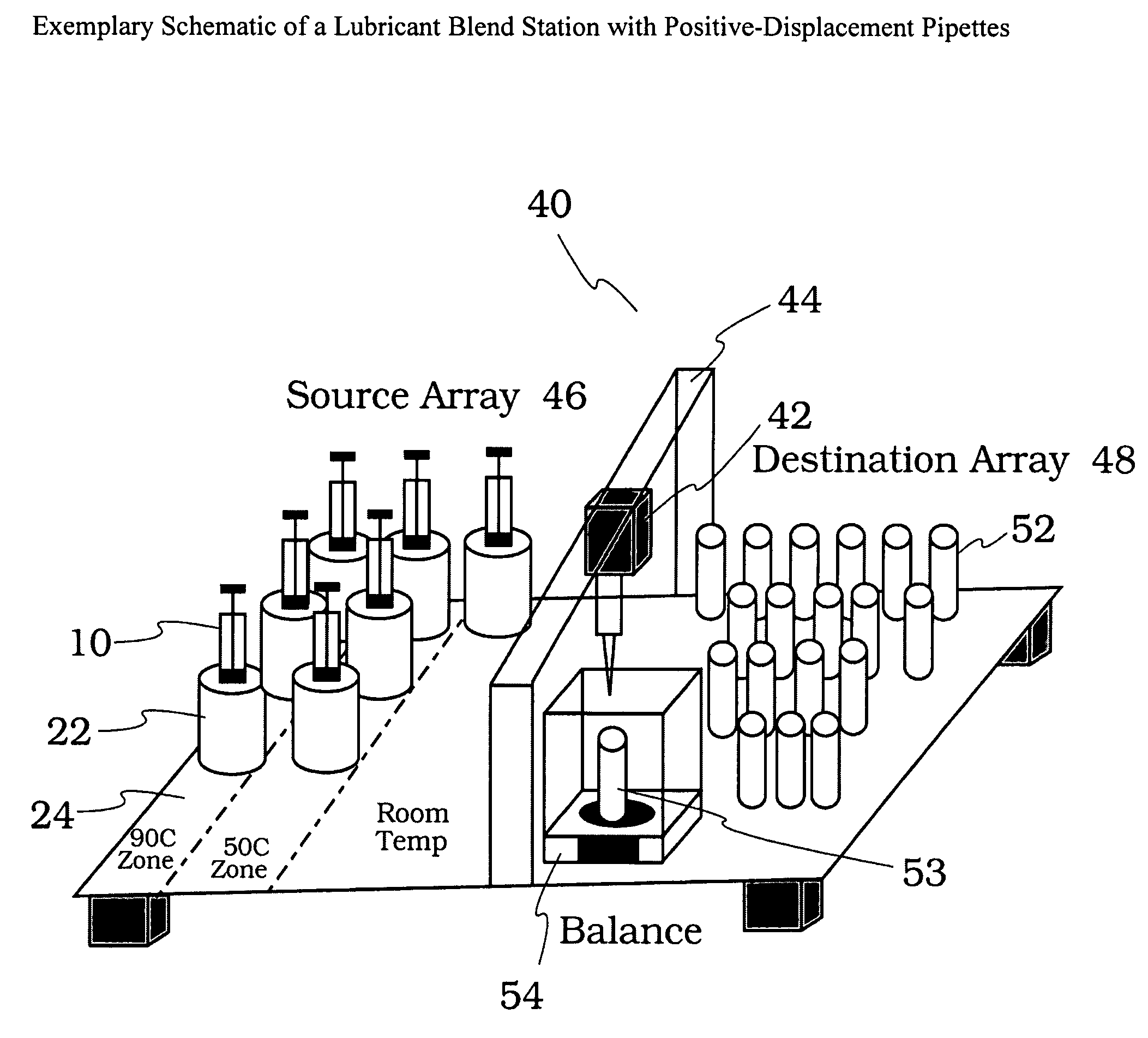
Method of blending lubricants using positive displacement liquid-handling equipment
a technology of liquid handling equipment and lubricant, which is applied in the field of lubricant blending, can solve the problems of requiring a high degree of accuracy, inaccuracy from several sources, and less liquid than desired being ejected from the pipette, and achieves the effects of low cost, less degradation and discoloration, and quick dispensing of small volumes
- Summary
- Abstract
- Description
- Claims
- Application Information
AI Technical Summary
Benefits of technology
Problems solved by technology
Method used
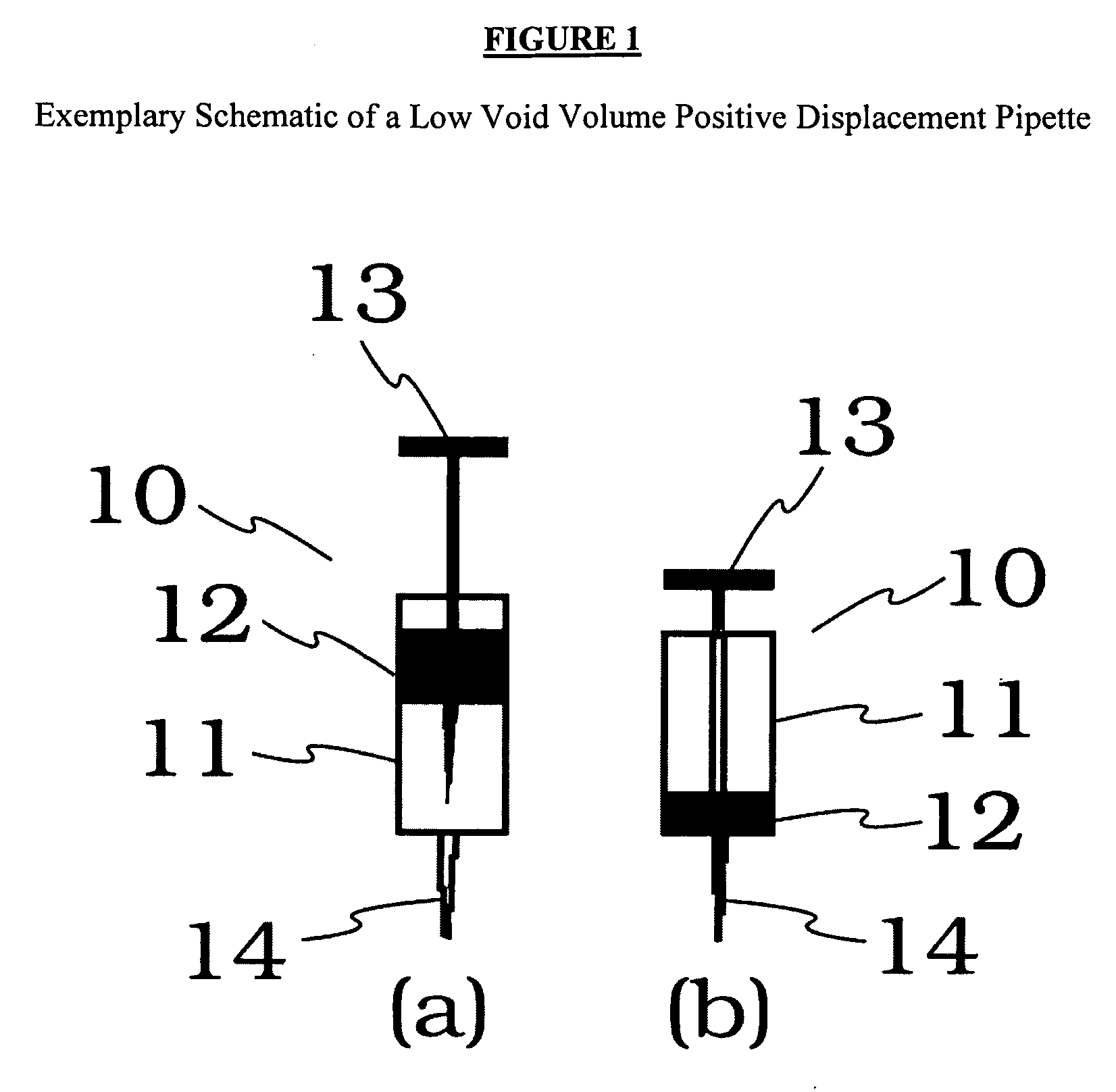
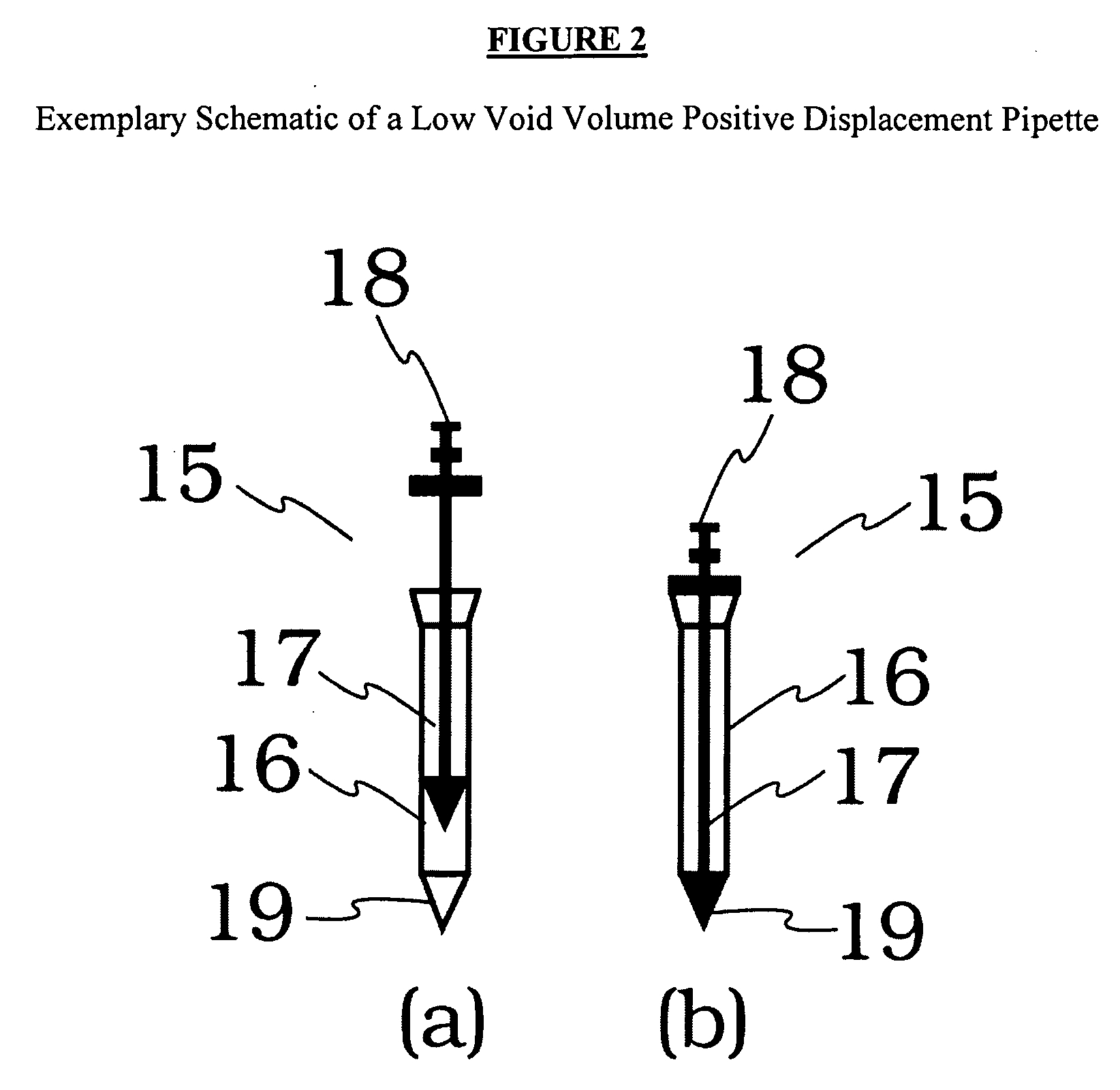
Image

Examples
example 1
[0081]Three lubricant additives were dispensed using the 10 μl Gilson Microman low void volume positive displacement pipettes (Type CP10) and the results are compared with those obtained using the Tecan Liquid Handling device which is based on air / liquid displacement. The descriptions and the typical properties of the additives used are given in Table 2.
TABLE 2Descriptions and Typical Properties of the Additives Used inExample 1InfineumParatone 8011Infineum D3426V387Additive TypeVI ImproverAdditivePour PointPackageDepressantKinematic Viscosity at102519085100 C., cStKinematic Viscosity at—411274040 C., cSt
[0082]It was found that the low void positive displacement pipettes Gilson Microman M10 gave excellent results at room temperature while the Tecan RSP100 liquid handling system could not handle the same components at room temperature. The results obtained using the Microman MIO is given in Table 3. In comparison, the data from the Tecan liquid handling system is given in Table 4.
TAB...
example 2
[0083]It was also found that Microman M100 (100 μl) low void positive displacement pipettes also gave excellent dispensing precision at room temperature when compared with Tecan RSP100 liquid handling system. The results obtained using the Microman M10 is given in Table 5. In comparison, the data from the Tecan liquid handling system is given in Table 6.
TABLE 5Dispensing Precision of the Microman M100 LVPDPs (Target100.0 μl, Room Temp)Paratone 8011Infineum D3426Infineum V387gramsgramsgramsDispense #10.0860.0940.086Dispense #20.08590.09390.0859Dispense #30.0860.09360.0856Dispense #40.08610.09350.0858Dispense #50:08590.09380.0861Dispense #60.0860.0940.0859Dispense #70.08610.09370.0858Dispense #80.0860.09350.0857Dispense #90.08610.09390.0856Dispense #100.08590.09360.0858Average0.0860.093750.08582Standard0.000080.000200.00016Deviation% Coefficient0.0950.2090.189of Variation
TABLE 6Dispensing precision of Tecan RSP100 liquid handling System(Target 125 μl, Room Temp)Paratone 8011Infineum D...
example 3
[0084]Paratone 8011 was dispensed at room temperature, 50° C. and 90° C. using 2.5 ml Jencons Scientific positive displacement pipettes (488-008) with and without modification. A razor blade was used to cut the pipette tip to remove the air space near the end of the tip. The modification reduces the void of the pipette. It was found that the modification leads to improvement in dispensing precision at room temperature and at 50° C. However at 90° C., no advantage was observed. The data are given in Table 7.
TABLE 7Dispense of Paratone 8011 at Room Temperature, 50° C., and 90° C.using 2.5 ml Jencons Scientific pipettes with and without modifications.Room Temp50° C.Modi-Modi-90° C.RegularfiedRegularfiedRegularModifiedPDPPDPPDPPDPPDPPDPgramsgramsgramsgramsgramsgramsDispense #12.1352.1672.1342.1412.1182.093Dispense #22.1522.1622.1452.1492.1202.121Dispense #32.1582.1632.1272.1462.1072.102Dispense #42.1662.1662.1282.1542.1182.099Dispense #52.1532.1522.1442.1582.1272.124Dispense #62.1392.17...
PUM
 Abstract
Description
Claims
Application Information