Focusing apparatus for optical device

a technology of optical devices and focusing apparatuses, applied in the field of optical devices, can solve the problems of inconvenient assembly of the focusing apparatus, inability to accurately work between the link arm and the guide member, and difficulty in installing the position sensor, so as to minimize manufacturing and assembly tolerances between parts

Inactive Publication Date: 2013-08-29
SAMSUNG ELECTRONICS CO LTD
View PDF7 Cites 8 Cited by
  • Summary
  • Abstract
  • Description
  • Claims
  • Application Information

AI Technical Summary

Benefits of technology

[0012]Accordingly, an exemplary aspect of the present invention provides a focusing apparatus which accurately delivers an operation of a driving motor to an operation of a lens barrel by minimizing manufacturing and assembly tolerances between parts.

Problems solved by technology

In large beam projectors which are generally provided as independent units and installed in public spaces such as halls, conference rooms, and so forth, a position sensor for sensing a position of a focus is installed, however in a miniaturized device such as a portable terminal, it is difficult to install the position sensor due to special restrictions.
However, in the focusing apparatus structured as described above, due to manufacturing and assembly tolerances between parts, interworking between the link arm and the guide members is not precise.
Moreover, due to the hysteresis caused by accumulated manufacturing and assembly tolerances between parts, during focusing, in spite of switch of the moving direction of the carriage, the lens barrel maintains a stationary state, such that even if the carriage moves in a direction and then returns to its initial position, the lens barrel fails to return to its initial position.
Furthermore, due to many restrictions in installation of the position sensor of the lens barrel in a miniaturized device such as a portable terminal, a difference between a movement distance of the carriage and a movement distance of the lens barrel makes it difficult to control the driving motor.
In addition, since the link arm and the guide member does not contact in a sufficient area to provide accurate rigid support, tilt of the lens barrel occurs during movement of the lens barrel as shown in FIG. 2, such that the lens barrel may become misaligned with respect to the optical axis.

Method used


Image

  • Focusing apparatus for optical device
  • Focusing apparatus for optical device
  • Focusing apparatus for optical device

Examples


Embodiment Construction

[0022]Hereinafter, an exemplary embodiment of the present invention will now be described in detail with reference to the accompanying drawings. In the following description, well-known functions or structures will not be described in detail if they may unnecessarily obscure appreciation of the subject matter of the present invention by a person of ordinary skill in the art. Also, the terms used herein are defined according to the functions of the present invention as would be understood by a person of ordinary skill in the art. Thus, the terms may vary depending on user's or operator's intension and usage. That is, the terms used herein must be understood based on the descriptions made herein in view of the ordinary level of skill in the art.

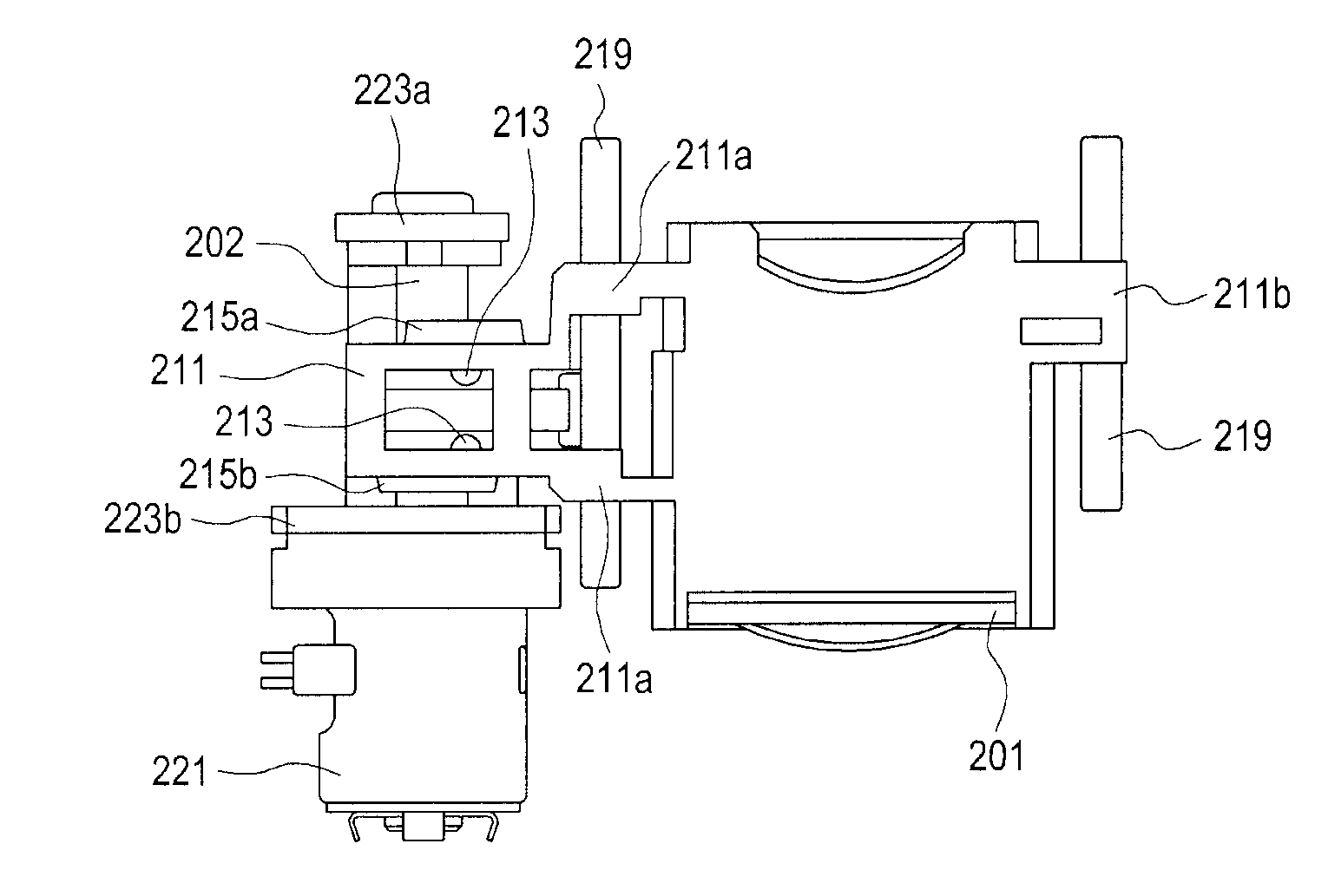
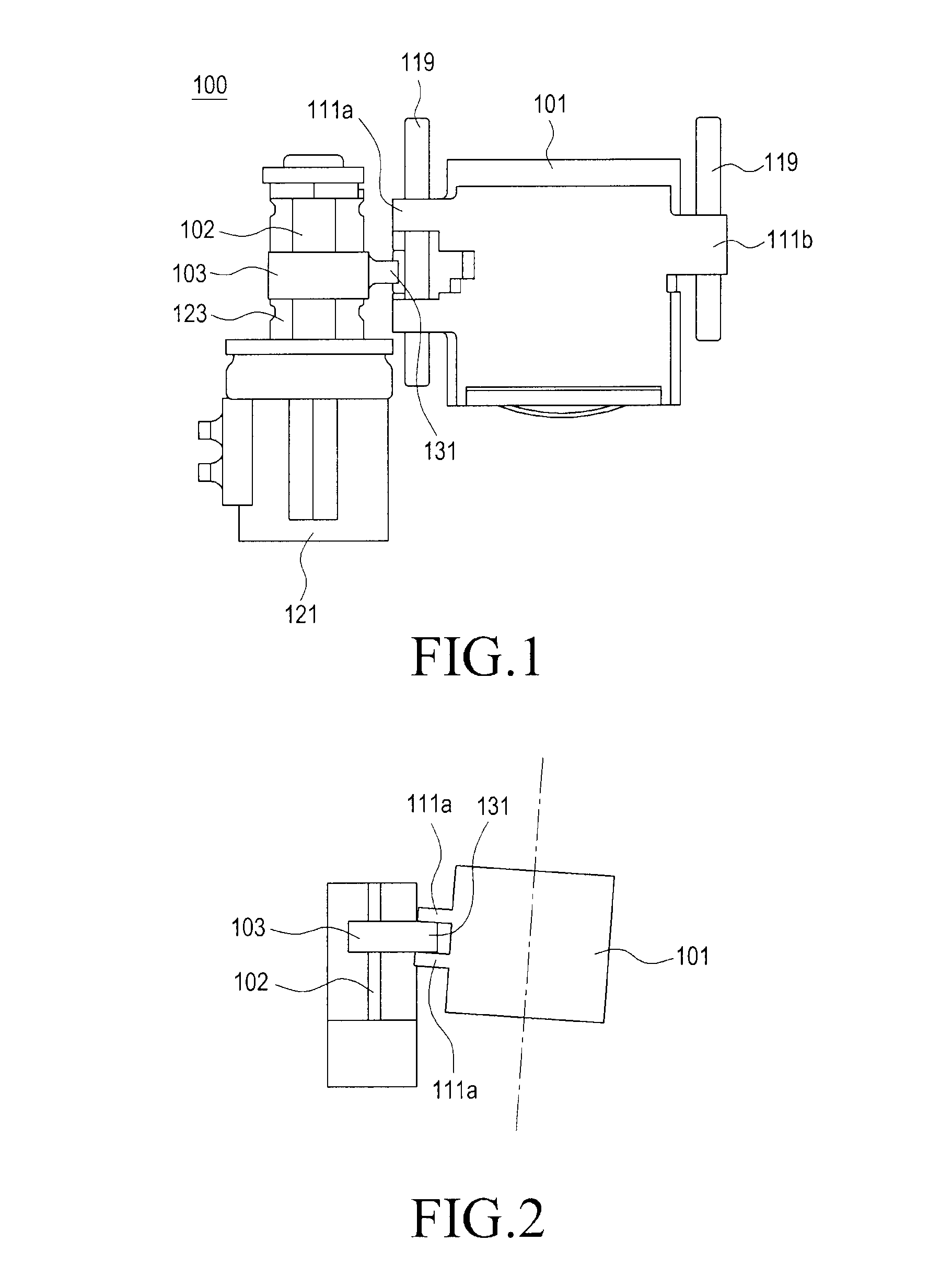
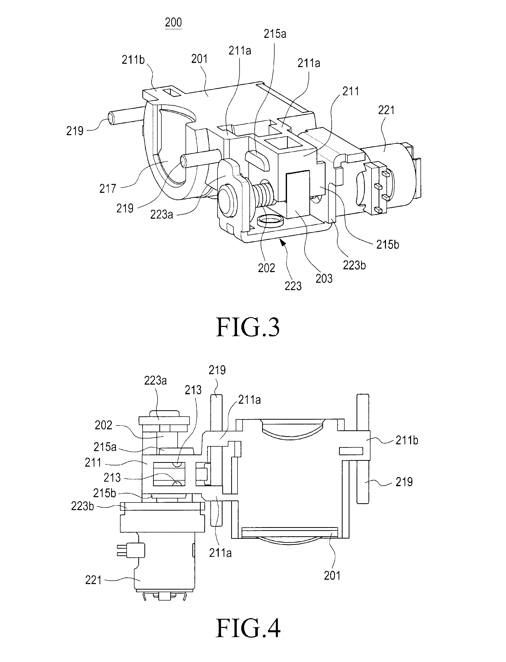
[0023]The present invention described hereinafter provides, as shown in FIGS. 3 through 6, a focusing apparatus 200 for an optical device which includes a lead screw 202, a carriage 203, a lens barrel 201, a bridge 211, and a protrusion portio...


PUM


Abstract

Provided is a focusing apparatus for an optical device, the focusing apparatus including a lead screw rotatably installed in the optical device, a carriage screw-coupled to the lead screw to move in a longitudinal direction of the lead screw in response to rotation of the lead screw, a lens barrel receiving at least one lenses and moving along the longitudinal direction of the lead screw, and a bridge extending from an outer circumferential surface of the lens barrel to enclose the carriage, in which the bridge moves the lens barrel in response to movement of the carriage.

Description

CLAIM OF PRIORITY[0001]This application claims the benefit under 35 U.S.C. §119(a) of a Korean Patent Application filed in the Korean Intellectual Property Office on Feb. 24, 2012 and assigned Serial No. 10-2012-0019069, the entire disclosure of which is hereby incorporated by reference.BACKGROUND OF THE INVENTION[0002]1. Technical Field of the Invention[0003]This disclosure generally relates to an optical device such as for example, but not limited to an image capturing device or a beam projector, and more particularly, to a focusing apparatus of a subminiature optical device which can be mounted on a small device such as a portable terminal.[0004]2. Description of the Related Art[0005]Optical devices may be classified into image capturing devices and image projecting devices such as beam projectors. The image capturing device includes an image sensor, while the image projecting device includes a light source and a liquid crystal panel, but they include in common a lens group inclu...

Claims


Application Information

Patent Timeline
Patent Type & Authority Applications(United States)
IPC IPC(8): G02B7/04
CPCG02B7/08G02B7/04G03B3/02G03B3/10
Inventor PARK, JOONG-WAN
Owner SAMSUNG ELECTRONICS CO LTD
Why Eureka
Try Eureka