Dual Accelerometer Plus Magnetometer Body Rotation Rate Sensor-Gyrometer

a magnetometer and accelerometer technology, applied in the field of smart devices, can solve the problems of gyroscopes that are often power hungry devices and require relatively large operating power, and gyroscopes are relatively expensive compared to other mems devices

Inactive Publication Date: 2013-08-29
MCUBE INC
View PDF7 Cites 13 Cited by
  • Summary
  • Abstract
  • Description
  • Claims
  • Application Information

AI Technical Summary

Benefits of technology

[0006]The present invention relates to the field of smart devices. More specifically, the present invention relates to determining rotational of such smart devices without relying upon MEMS-based gyroscopes. In particular, embodiments of the present include utilizing acceleration data from one or more accelerometers, and magnetic field data from a magnetometer of the smart device to compute rotational manipulation of the smart device. In various embodiments, such acceleration data and magnetic field data are combined with known geometry of the accelerometers / magnetometer within the smart device. In some embodiments, the distances and directions of the accelerometers and magnetometer with respect to each other, a center of gravity, or the like may be used in the computations.
[0007]According to one aspect of the invention, a computer-system implemented method for determining gyroscopic rotation data, implemented on a computer system programmed to perform the method is disclosed. One technique includes determining in one or more accelerometers of the computer system, accelerometer data in response to a physical manipulation of the computer system, and determining in a magnetometer of the computer system, magnetometer data in response to the physical manipulation of the computer system. A process includes determining in the processor of the computer system, a gyroscopic rotation of the computer system in response to the accelerometer data and to the magnetometer data.
[0008]According to one aspect of the invention, a mobile computer-system for determining rotation data is disclosed. An apparatus includes one or more accelerometers configured to determine accelerometer data in response to a physical manipulation of the mobile computer system, and a magnetometer configured to determine magnetometer data in response to the physical manipulation of the mobile computer system. A device includes a processor coupled to the one or more accelerometers and to the magnetometer, wherein the processor is programmed to determine a rotation of the mobile computer system in response to the accelerometer data ad to the magnetometer data.

Problems solved by technology

One such drawback is that gyroscopes are often power hungry devices that require relatively large operating power, compared to other MEMS devices, such as accelerometers.
Another drawback is that gyroscopes are relatively expensive compared to other MEMS devices.

Method used


Image

  • Dual Accelerometer Plus Magnetometer Body Rotation Rate Sensor-Gyrometer
  • Dual Accelerometer Plus Magnetometer Body Rotation Rate Sensor-Gyrometer
  • Dual Accelerometer Plus Magnetometer Body Rotation Rate Sensor-Gyrometer

Examples


Embodiment Construction

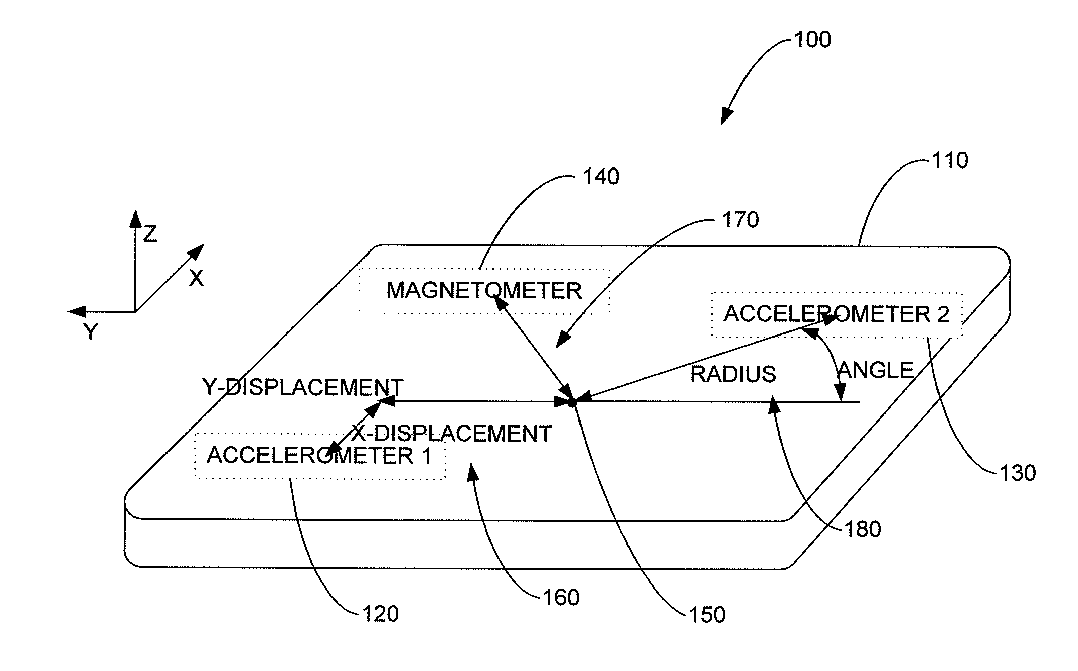
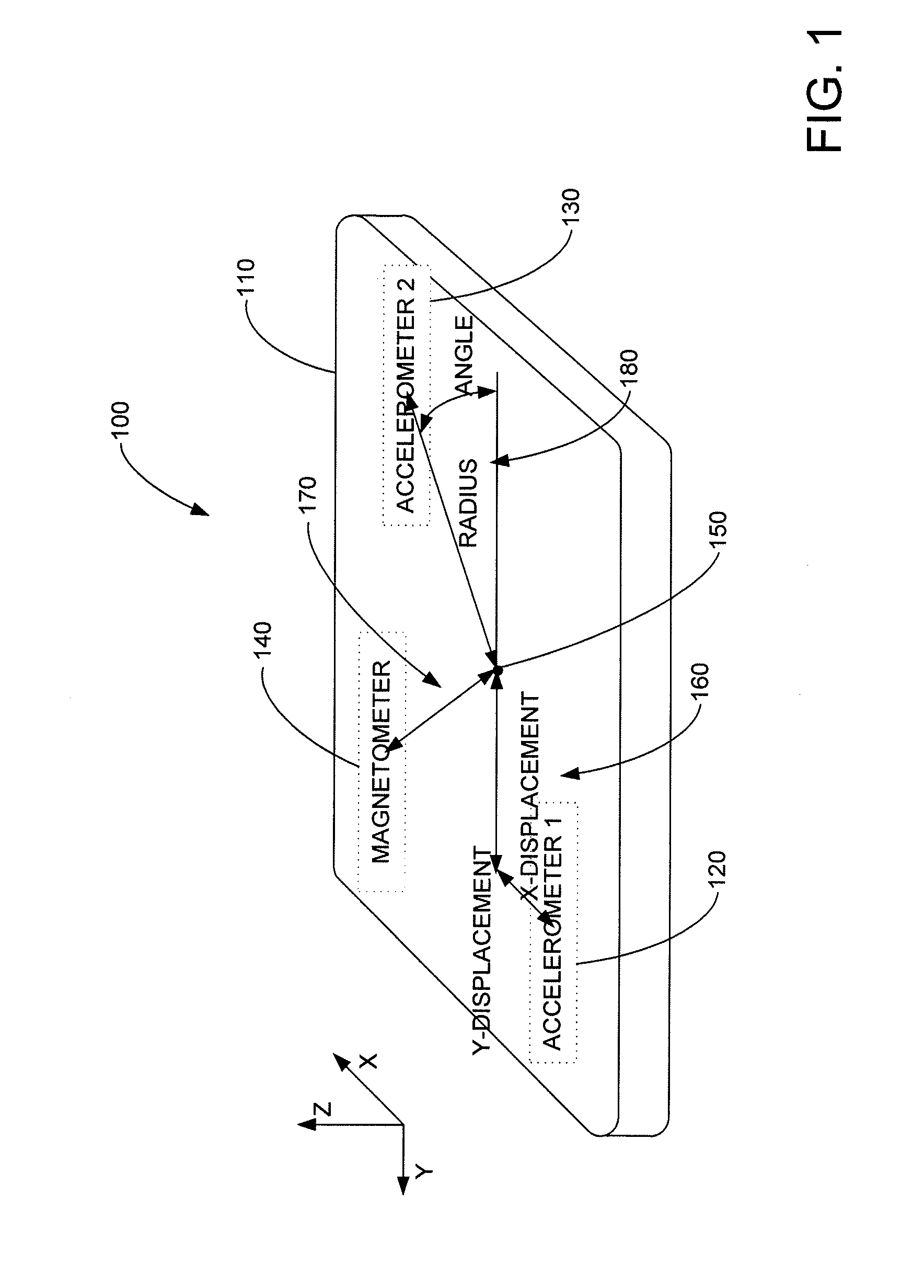
[0013]FIG. 1 illustrates a functional block diagram according to various embodiments of the present invention. More specifically, FIG. 1 illustrates a device 100, e.g. smart phone, or the like, having a body 110.

[0014]Within device 100 MEMs-based accelerometers 120 and 130 and magnetometer 140 are included. As shown, a reference point 150 is identified within device 100. In some embodiments, point 150 may be a computed center-of gravity, an axis of rotation, or the like.

[0015]In various embodiments, offsets, displacements or the like 160, 170 and 180 are respectively is determined between point 150 and accelerometer 120, accelerometer 130, and magnetometer 140. In some embodiments, offsets 160, 170 and 180 may be computed during the design phase, production phase, or the like. In some embodiments, offsets 160, 170 and 180 can be stored within a memory of device 100 and used for the computations described below. In other embodiments, one or more look-up-tables may be used that receiv...


PUM


Abstract

A computer-system implemented method for determining gyroscopic rotation data, implemented on a computer system programmed to perform the method includes determining in one or more accelerometers of the computer system, accelerometer data in response to a physical manipulation of the computer system, determining in a magnetometer of the computer system, magnetometer data in response to the physical manipulation of the computer system, and determining in the processor of the computer system, a gyroscopic rotation of the computer system in response to the accelerometer data and to the magnetometer data.

Description

CROSS REFERENCE TO RELATED APPLICATIONS[0001]The present application is a non-provisional of 61 / 594,336 filed Feb. 2, 2012 and incorporates it by reference, for all purposes.BACKGROUND OF THE INVENTION[0002]The present invention relates to the field of smart devices. More specifically, the present invention relates to determining rotational manipulations of such smart devices.[0003]Three-axis gyroscopes have been useful for determining rotations of hand-held devices about three-axes. The inventors of the present invention have determined that there are several drawbacks to the use of such gyroscopes in hand-held devices to determine rotations. One such drawback is that gyroscopes are often power hungry devices that require relatively large operating power, compared to other MEMS devices, such as accelerometers. Another drawback is that gyroscopes are relatively expensive compared to other MEMS devices. Although many current smart-devices, e.g. phones, tablets, etc. include such gyro...

Claims


Application Information

Patent Timeline
Patent Type & Authority Applications(United States)
IPC IPC(8): G01C19/02
CPCG01P7/00G01C25/005G01P9/02G01C19/00
Inventor KELLY, JOEACHESON, JOHN
Owner MCUBE INC
Why Eureka
Try Eureka