Image forming apparatus

a technology of image forming apparatus and forming tube, which is applied in the direction of electrographic process apparatus, instruments, optics, etc., can solve the problems of image quality of the image forming apparatus, and achieve the effect of image forming

Inactive Publication Date: 2013-09-12
CANON KK
View PDF1 Cites 10 Cited by
  • Summary
  • Abstract
  • Description
  • Claims
  • Application Information

AI Technical Summary

Benefits of technology

[0008]Therefore, an image forming apparatus can be increased in image quality by optimizing the combination, in terms of positional relationship in terms of the direction perpendicular to the toner image conveyance direction, between the range across which the untreated (unhardened) portion of the image bearing member cleaning blade is placed in contact with the image bearing member, and the range across which the untreated (unhardened) portion of the intermediary transfer member is placed in contact with the intermediary transfer member, in order to make it difficult for the residual toner on its image bearing member and intermediary transfer member to escape.

Problems solved by technology

Further, the greater the amount by which the residual toner slips by the image bearing member cleaning blade, the greater the amount by which the residual toner remains adhered to the intermediary transfer member, and therefore, the lower the image forming apparatus will be in image quality.

Method used


Image

  • Image forming apparatus
  • Image forming apparatus
  • Image forming apparatus

Examples


embodiment 1

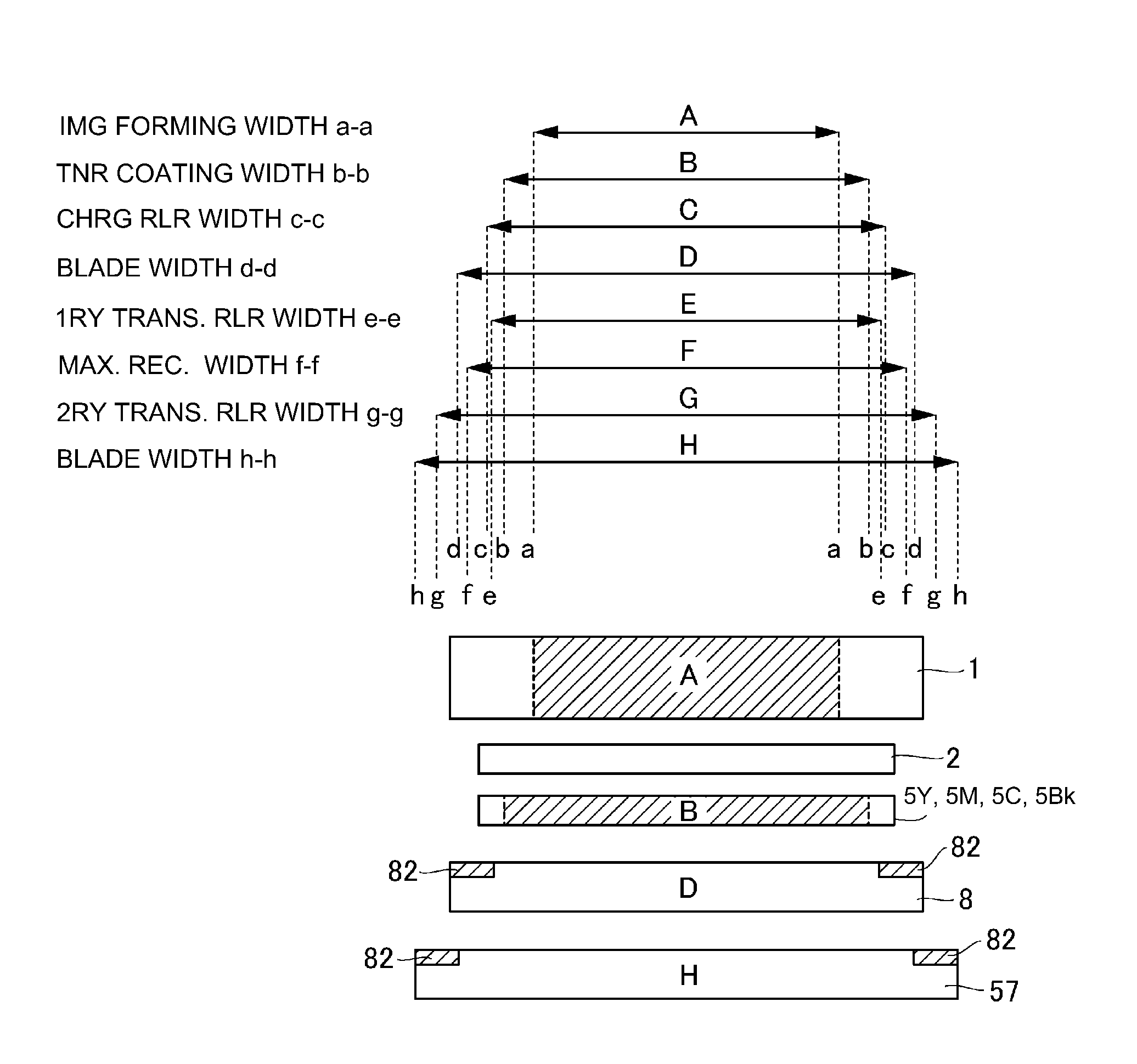
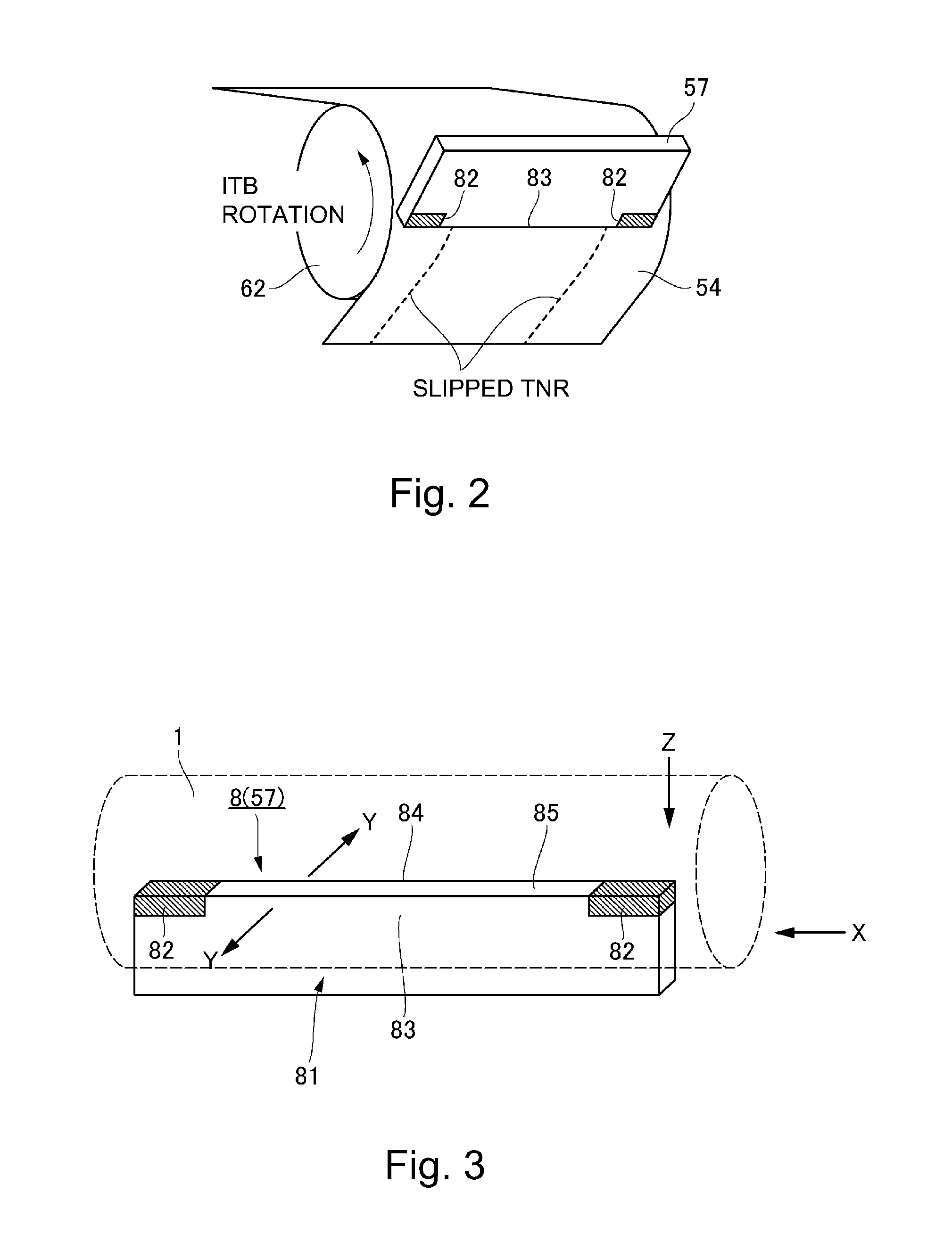
[0073]FIG. 7 is a schematic drawing for describing the positional relationship among the cleaning blades 8, charge roller 2, and their various portions (untreated and treated portions, transitional portions, etc.), in the first embodiment of the present invention, in terms of the lengthwise direction of the cleaning blade 8 (charge roller 2). FIG. 8 is a schematic drawing for describing the positional relationship between the untreated portion 83 of the cleaning blade 8, and the untreated portion 83 of the cleaning blade 57, in terms of the lengthwise direction of the blades 8 and 57.

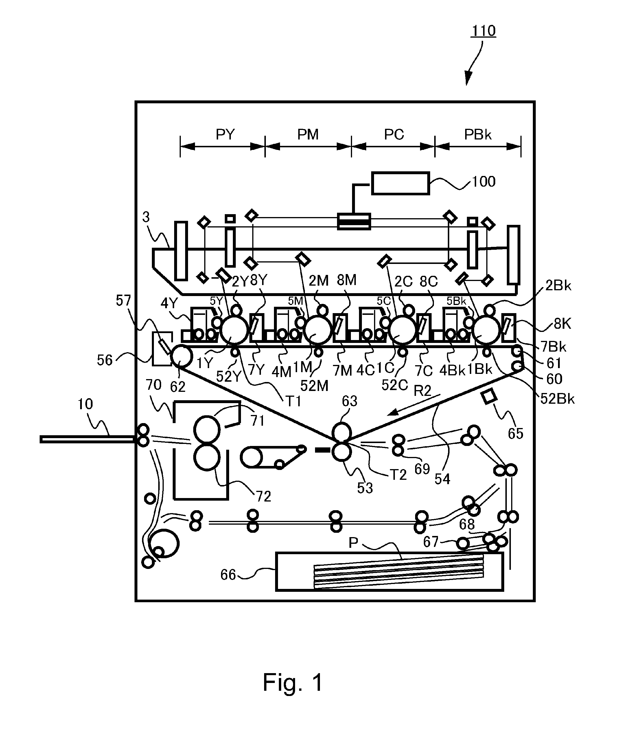
[0074]Referring to FIG. 1, the intermediary transfer belt 54 which is an example of an intermediary transfer member is placed in contact with the peripheral surface of the photosensitive drum 1 in the primary transfer station T1, in which the toner image on the peripheral surface of the photosensitive drum 1 is transferred onto the intermediary transfer belt 54. The drum cleaning device 7 which is an ex...

embodiment 2

[0100]FIG. 9 is a schematic drawing for describing the positioning of the cleaning blade of the drum cleaning device in the second embodiment. Referring to FIG. 9, in the case of the image forming apparatus in the second embodiment, the transitional portion between the treated (hardened) portion 82 and untreated portion 83 of each of the cleaning blades 8Y, 8M, 8C and 8Bk in the image forming stations PY, PM, PC and PBk, respectively, does not coincide in position in terms of the lengthwise direction of the cleaning blades; it does not align with those of the other cleaning blades 8 in terms of the rotational direction of the photosensitive drums 1.

[0101]In the second embodiment, the image formation stations PY, PM, PC and PBk having photosensitive drums 1Y, 1M, 1C and 1Bk, and cleaning devices 7Y, 7M, 7C and 7Bk, respectively, are aligned along the intermediary transfer belt 54. The cleaning blades 8Y, 8M, 8C and 8Bk are different in the dimension of their unhardened portion, in te...

embodiment 3

[0105]FIG. 10 is a schematic drawing for describing the positional relationship between the treated (hardened) portion 82 of the cleaning blade 8, and the charge roller 2, in the third embodiment. FIG. 11 is a schematic drawing for describing the positional relationship between the treated (hardened) portion 82 of the cleaning blade 8, and charge roller 2, of the fourth comparative image forming apparatus.

[0106]In the third embodiment, the dimension of the untreated portion 83 (P), that is, the portion between the treated (hardened) portions, of the cleaning blade 8 was made less than the dimension of the of the charge roller 2, in terms of the direction perpendicular to the toner image conveyance direction.

[0107]Referring to FIG. 7, the length of the charge roller 2 equals the dimension of the range C of the photosensitive drum 1, which is chargeable with the charge roller 2. The end of the range C is indicated by a referential code c, the width c-c of the range C is 319 mm. In com...


PUM


Abstract

Image forming apparatus includes first cleaning blade for photosensitive drum, wherein the first blade includes first regions and second region with respect to widthwise direction, the first regions being at opposite ends of the first blade, respectively and having first hardness, and the second region being between the first regions and having hardness which is lower than the first hardness; and second cleaning blade for the intermediary transfer member, wherein the second blade includes third regions and fourth region with respect to the widthwise direction, the third regions being at opposite ends of the second blade, respectively and having a second hardness which is the same as or different from the first hardness, and the fourth region being between the third regions and having hardness lower than the second hardness, and wherein the second region is within the fourth region with respect to the widthwise direction.

Description

FIELD OF THE INVENTION AND RELATED ART[0001]The present invention relates to an image forming apparatus, which employs a pair of cleaning blades, which are hardened across their lengthwise end portions and are placed in contact with the image bearing member and intermediary transferring member (or the like), one for one.[0002]There has been widely used an image forming apparatus which forms a toner image, transfers the toner image onto recording medium with the use of an intermediary transferring member or a recording medium conveying member, and fixes the transferred toner image on the recording medium by applying heat and pressure to the recording medium and the toner image thereon with the use of a fixing device. Such an image forming apparatus employs a cleaning device for recovering transfer residual toner, that is, the toner remaining adhered to the image bearing member and / or intermediary transferring member (or the like) after the transfer of a toner image from the image bea...

Claims


Application Information

Patent Timeline
Patent Type & Authority Applications(United States)
IPC IPC(8): G03G15/16G03G21/00
CPCG03G15/161G03G15/095G03G21/0017
Inventor KOMATSU, ISAO
Owner CANON KK
Why Eureka
Try Eureka