
Structure mounted airbag assemblies and associated systems and methods

a technology of airbags and assemblies, applied in the direction of vehicular safety arrangments, pedestrian/occupant safety arrangements, seating arrangements, etc., can solve the problems of not being as effective in other types of vehicles having other seating arrangements, unsuitable for airbag storage, and rapid inflating of airbags

Active Publication Date: 2013-09-19
AM SAFE
View PDF6 Cites 15 Cited by
  • Summary
  • Abstract
  • Description
  • Claims
  • Application Information

AI Technical Summary

Benefits of technology

The patent describes a structure mounted airbag system for aircraft and other vehicles that can provide protection for passengers in the event of a crash or rapid deceleration event. The system includes a housing that is positioned forward of and offset from the passenger seat, with an airbag mounted behind a covered opening. The airbag deploys through the opening during a crash or rapid deceleration event, reducing the impact experienced by the occupant. The system is designed to avoid direct contact with out-of-position seat occupants and small children. The patent also describes different embodiments of the system that can be used in various vehicles.

Problems solved by technology

This causes the inflator to release compressed gas into the airbag, thereby rapidly inflating the airbag.
Although airbags that deploy from stationary locations (e.g., a steering column) may be effective in automobiles, they may not be as effective in other types of vehicles having other seating arrangements.
The aircraft seatbacks may also rotate forward and downward during a crash or similar event, and thus may be unsuitable for airbag storage.

Method used


Image

  • Structure mounted airbag assemblies and associated systems and methods
  • Structure mounted airbag assemblies and associated systems and methods
  • Structure mounted airbag assemblies and associated systems and methods

Examples


Embodiment Construction

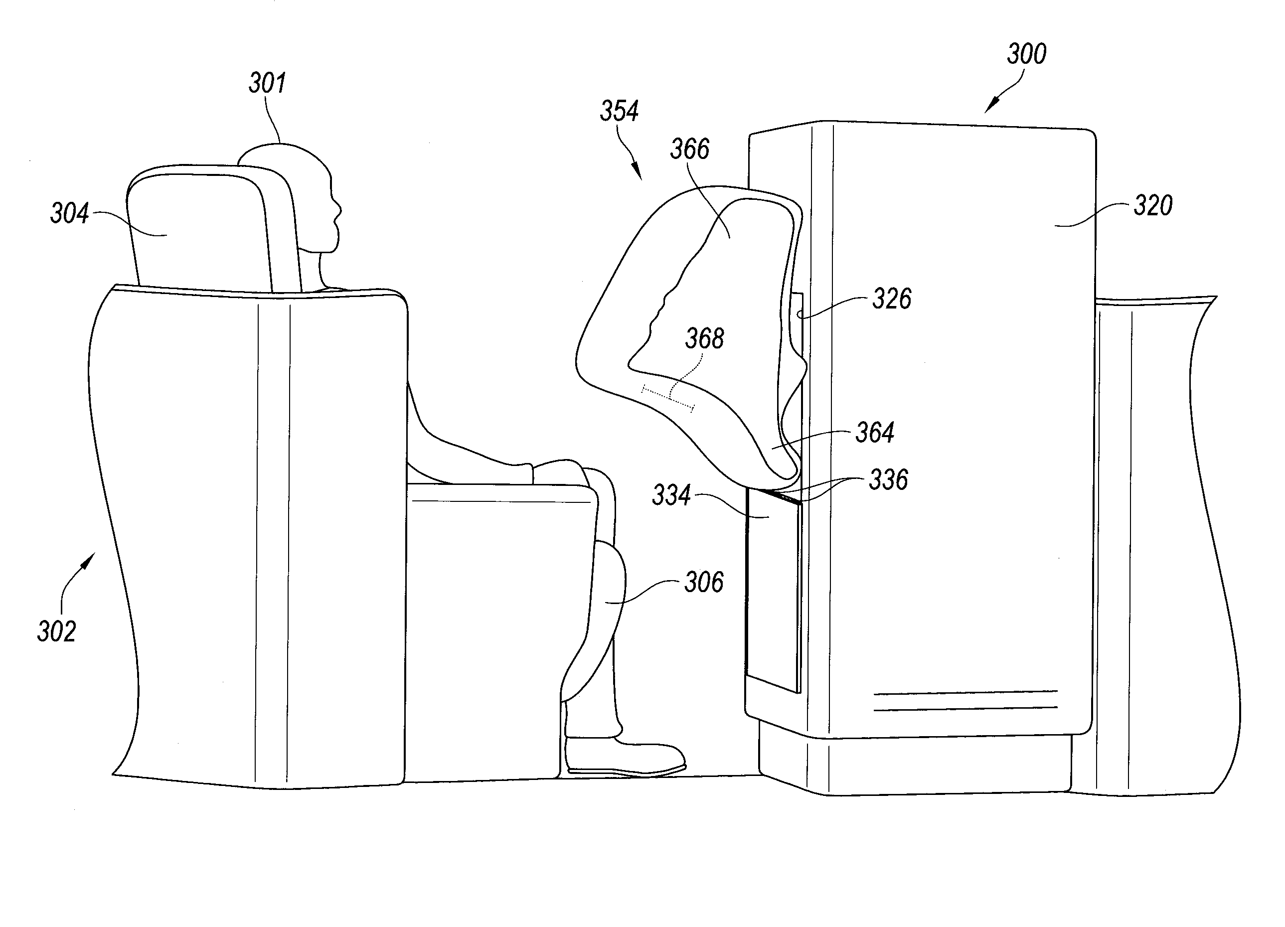
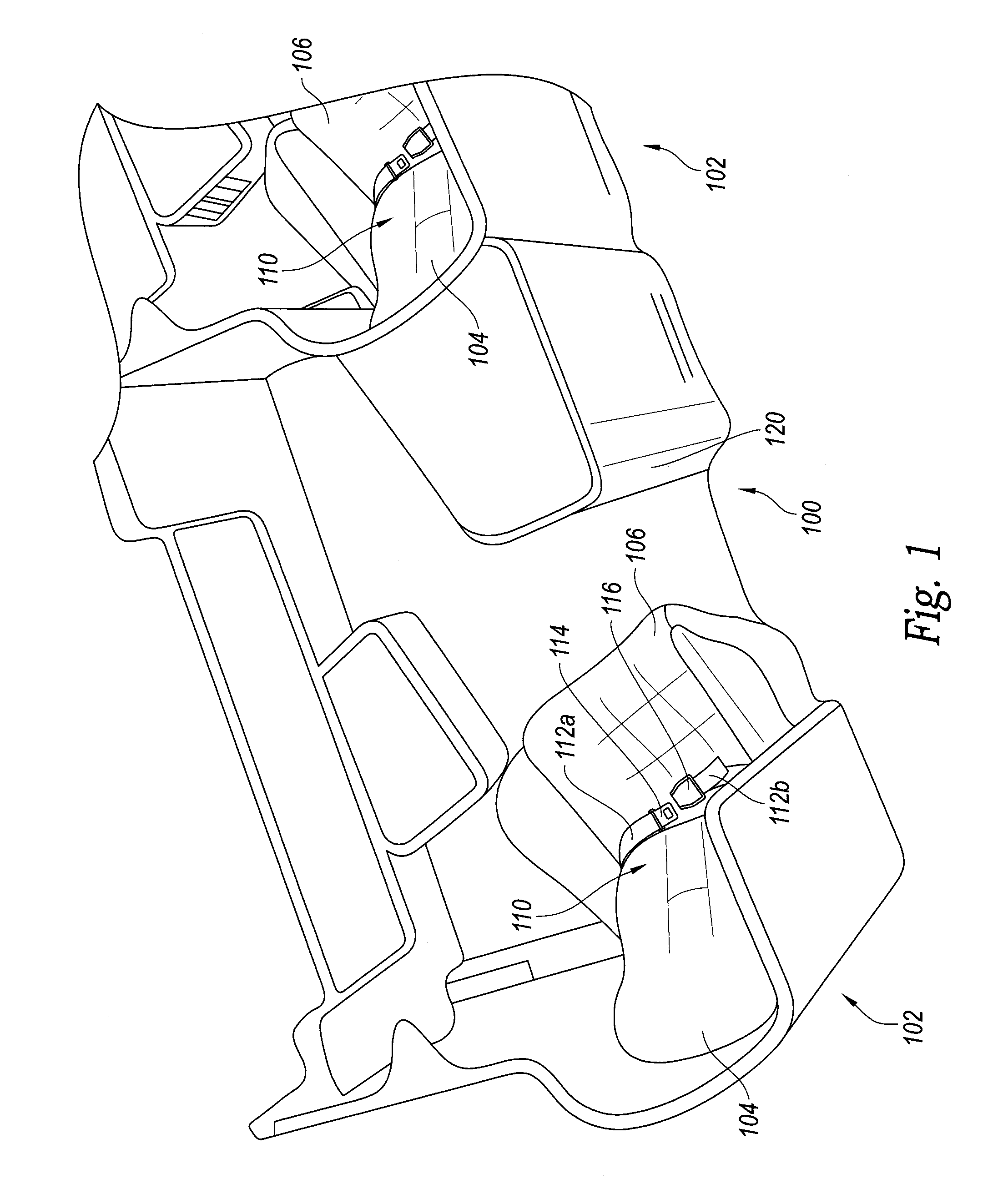
[0010]The present disclosure describes structure mounted air bag assemblies for use in, e.g., aircraft and associated systems and methods. In several embodiments, for example, a structure mounted airbag system in a commercial aircraft can include a housing positioned forward of and offset from a passenger seat. The housing can contain an airbag mounted behind a covered opening. During a crash or rapid deceleration event, the airbag can deploy through the opening toward the seat to reduce the impact experienced by the occupant. Since the structure mounted airbag system is offset from the vehicle seat, the airbag deploys in a manner that avoids direct contact with out-of-position seat occupants, such as occupants in the brace position (i.e., occupants with their head between their knees) and small children (e.g., children seated in a child seat or lap-held children). As used herein, the terms “structure mounted” and “structure mountable” refer to features that are or can be mounted to...


PUM


Abstract

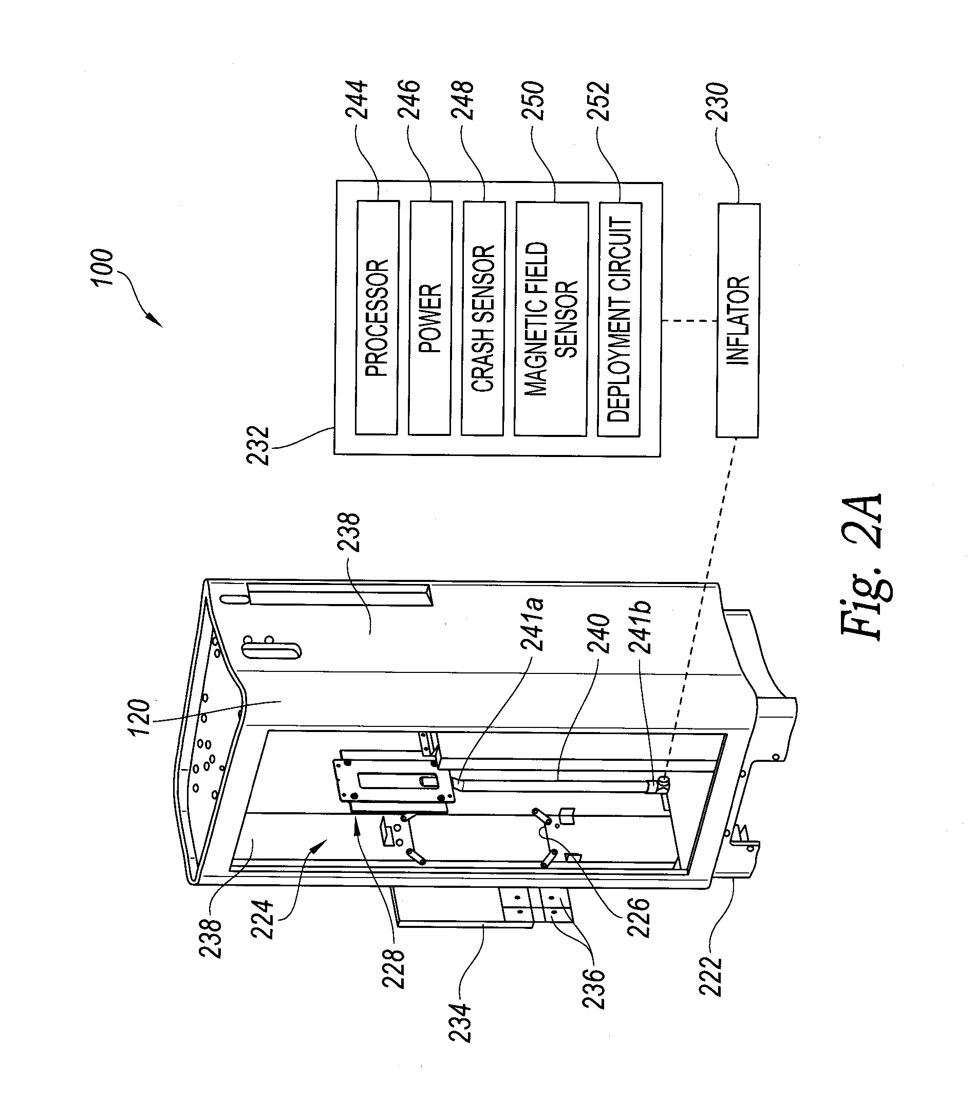
Structure mounted airbag assemblies and associated systems and methods are described herein. An airbag system configured in accordance with an embodiment of the present disclosure can include, for example, a housing having a cavity and an opening in communication with the cavity, an airbag assembly within the cavity, and an inflator operably coupled to the airbag assembly. The airbag assembly can include an airbag configured to deploy through the opening of the housing during a crash event. The airbag system can further include a door removably positioned across the opening and configured to move away from the opening during airbag deployment. The housing can be affixed to an interior portion of an aircraft, forward of and offset from an aircraft seat.

Description

TECHNICAL FIELD[0001]The following disclosure relates generally to vehicle safety systems, and more specifically to structure mounted airbag assemblies for aircraft and associated systems and methods.BACKGROUND[0002]Various types of seat belt and airbag systems have been used to protect passengers in automobiles, aircraft and other vehicles. In automobiles, for example, airbags typically deploy from the steering column, dashboard, side panel, and / or other fixed locations. During a rapid deceleration event (e.g., a collision), a sensor detects the event and transmits a corresponding signal to an initiation device (e.g., a pyrotechnic device) on an airbag inflator. This causes the inflator to release compressed gas into the airbag, thereby rapidly inflating the airbag.[0003]Although airbags that deploy from stationary locations (e.g., a steering column) may be effective in automobiles, they may not be as effective in other types of vehicles having other seating arrangements. Seats in ...

Claims


Application Information

Patent Timeline
Patent Type & Authority Applications(United States)
IPC IPC(8): B60R21/16
CPCB64D11/06B64D11/0604B64D11/06205B64D2201/00B64D11/0621B60R21/20B60R21/231B60R21/26B60R2021/0093
Inventor GEHRET, WILLIAM J.VYROSTEK, JOSHUAKEESLAR, KEVIN J.FOUBERT, DANIEL N.
Owner AM SAFE
Learn More