Dynamic lighting control

a lighting control and dynamic technology, applied in the field of lighting, can solve the problems of time-consuming, disruptive to operations, high cost, and special expertise, and achieve the effect of not being able to automatically control the lighting, and reducing the cost of operation

Inactive Publication Date: 2013-09-19
GENERAL ELECTRIC CO
View PDF10 Cites 22 Cited by
  • Summary
  • Abstract
  • Description
  • Claims
  • Application Information

AI Technical Summary

Problems solved by technology

This often requires rewiring of a facility, which can be time-consuming, disruptive to operations, and expensive.
Additionally, once the lighting control system is installed, commissioning and maintenance are required, and this can be expensive and involves special expertise.
Moreover, the lighting control may not be automatic and requires input in order to control the luminosity in a room.
Further, although wireless communication systems can be installed, the lighting control is still not aut...

Method used


Image

  • Dynamic lighting control
  • Dynamic lighting control
  • Dynamic lighting control

Examples


Embodiment Construction

[0024]Reference now will be made in detail to embodiments of the invention, one or more examples of which are illustrated in the drawings. Each example is provided by way of explanation of the invention, not limitation of the invention. In fact, it will be apparent to those skilled in the art that various modifications and variations can be made in the present invention without departing from the scope or spirit of the invention. For instance, features illustrated or described as part of one embodiment can be used with another embodiment to yield a still further embodiment. Thus, it is intended that the present invention covers such modifications and variations as come within the scope of the appended claims and their equivalents.

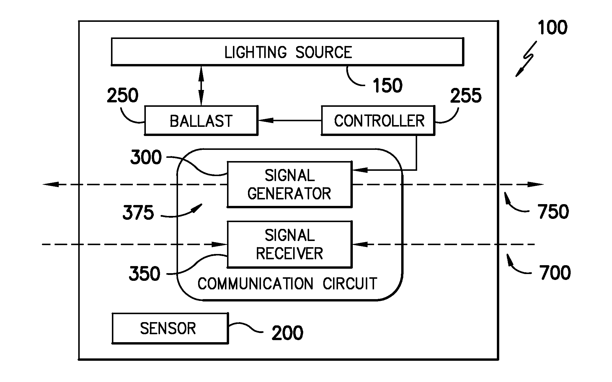
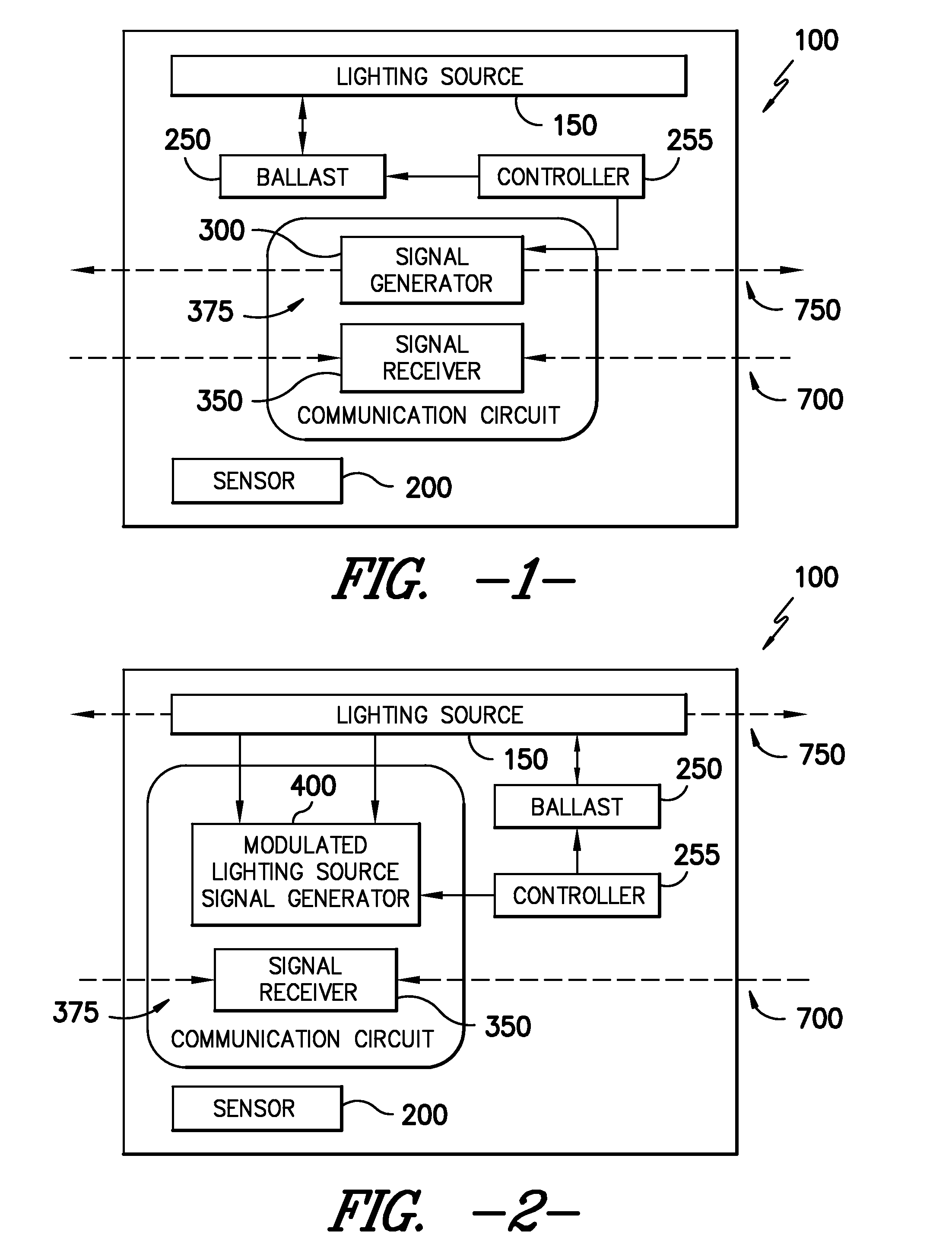
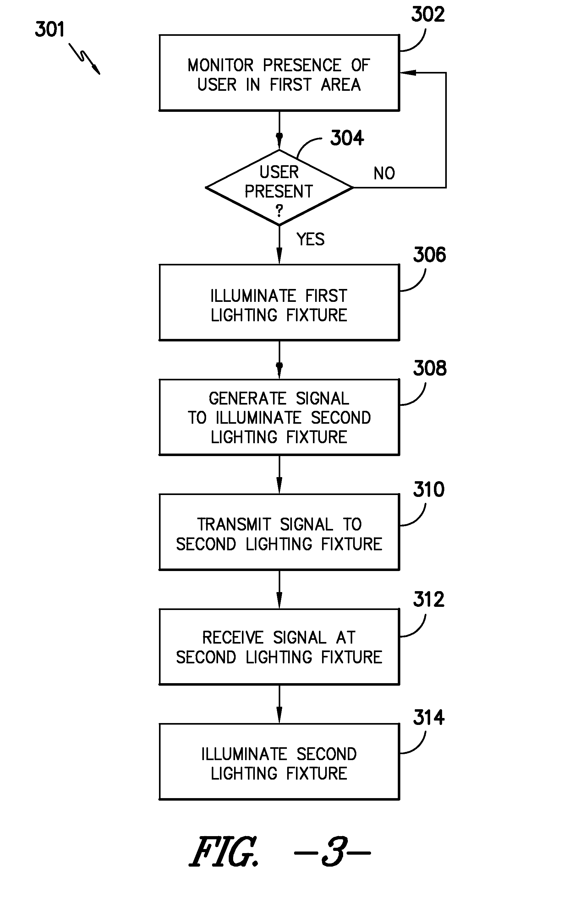
[0025]Generally, the present disclosure relates to an occupancy or motion-based dynamic lighting control system and method. The system can include at least two lighting fixtures that can communicate with each other over a wireless communication channel and / ...


PUM


Abstract

The present subject matter is directed to a lighting control system and method. Motion or occupancy sensors are used to determine when a lighting fixture and/or a nearby lighting fixture should be activated. A controller associated with each lighting fixture switches its lighting fixture on and triggers a communications circuit to generate and send a signal to nearby lighting fixtures when a user is detected. Each lighting fixture also has a signal receiver to receive signals from any nearby lighting fixtures that are configured to communicate with it via a communication circuit. The present subject matter allows for a significant amount of energy to be saved as remote areas away from an occupied area do not have to be illuminated. Meanwhile, the user is still provided with a comfortable level of lighting in and near the occupied area.

Description

BACKGROUND OF THE INVENTION[0001]A. Field of the Invention[0002]The present subject matter relates to lighting. More particularly, the present subject matter relates to a lighting control system and method.[0003]B. Description of Related Art[0004]In large buildings or outdoor spaces, it is often desirable to provide a control system for the lighting in the building or outdoor space in order to reduce energy costs. Currently, lighting in an area such as a corridor or room, can be controlled by various means such as from a central location, by remote control, or by motion detection. Centrally located lighting control systems can require the integration of sensors and lighting drivers into a dedicated analogue / digital / communications system such as can be implemented by the digital addressable lighting interface (DALI) protocol. This often requires rewiring of a facility, which can be time-consuming, disruptive to operations, and expensive. Additionally, once the lighting control system...

Claims


Application Information

Patent Timeline
IPC IPC(8): H05B37/02
CPCH05B37/0227Y02B20/44H05B37/0245H05B47/175Y02B20/40H05B47/115
Inventor BAL ZS, LASZLOKERCSO, BERTALANMAROS, ISTVAN
Owner GENERAL ELECTRIC CO
Why Eureka
Try Eureka