Heating device

a technology of heating device and heat sink, which is applied in the direction of ohmic resistance heating, electrical heating, electrical apparatus, etc., can solve the problems of substantial impact on the overall production cost of the device, subject to breakage, and cost, and achieve the effect of simple and direct connection

Inactive Publication Date: 2013-09-26
THERMO ENG
View PDF4 Cites 0 Cited by
  • Summary
  • Abstract
  • Description
  • Claims
  • Application Information

AI Technical Summary

Benefits of technology

[0010]The technical task of the present invention is therefore to devise a heating device that can be installed and made to work in rooms of any type without any transformer, i.e., with a simple and direct connection to the electrical mains.

Problems solved by technology

However, the transformer is a component whose cost has a substantial impact upon the overall production cost of the device, and also clearly on the installation and maintenance cost thereof, since it must be suitably installed, it can be subject to breaking, etc.

Method used


Image

  • Heating device
  • Heating device
  • Heating device

Examples


Embodiment Construction

.

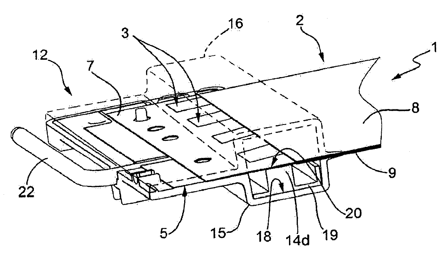
[0029]With reference to the attached FIG. 1, a heating device according to the present invention is wholly indicated with 1.

[0030]The heating device according to the present invention can be installed in any room, public or private, without any limitation, and it can be mounted under the surface of any wall or floor.

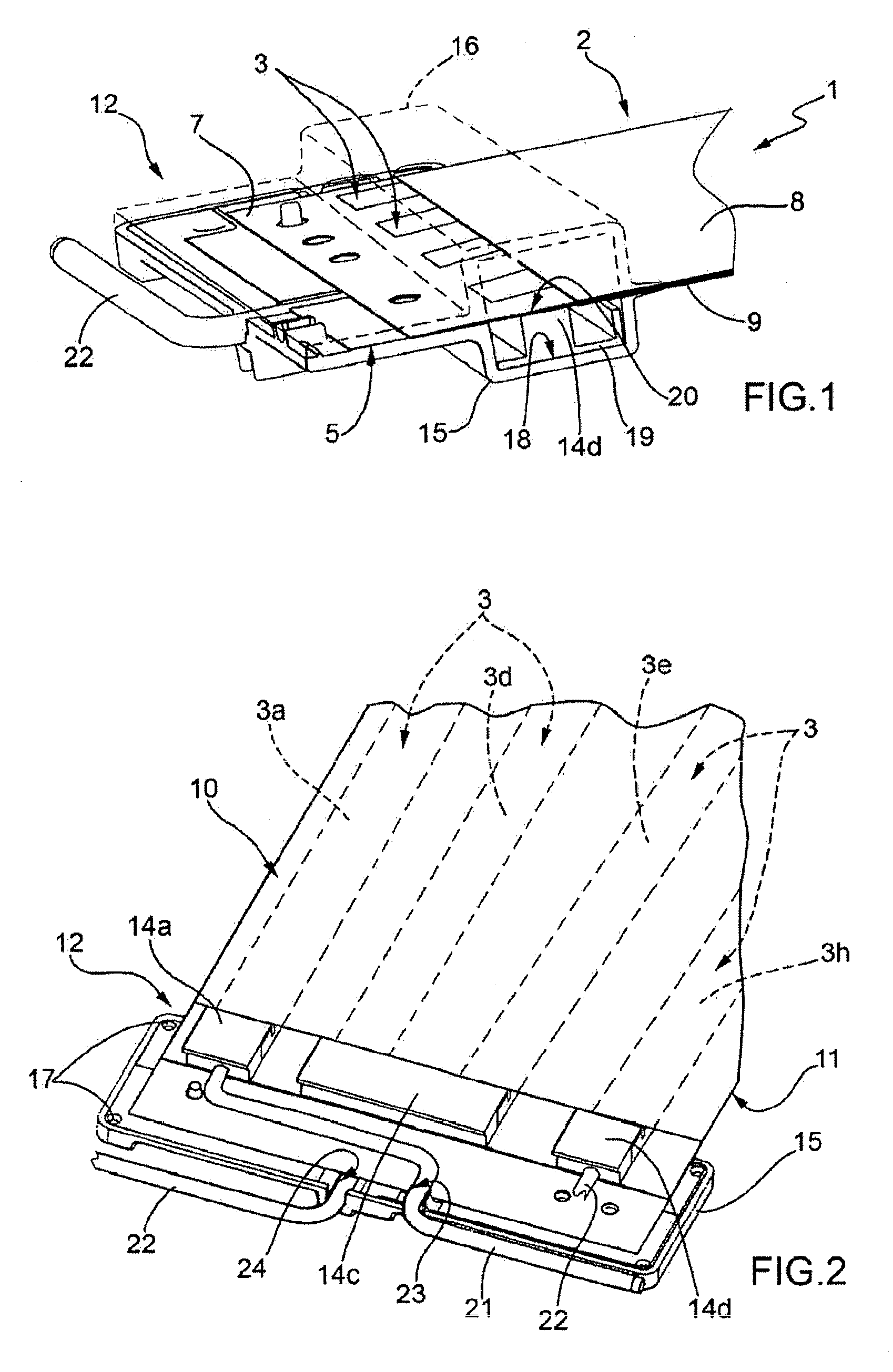
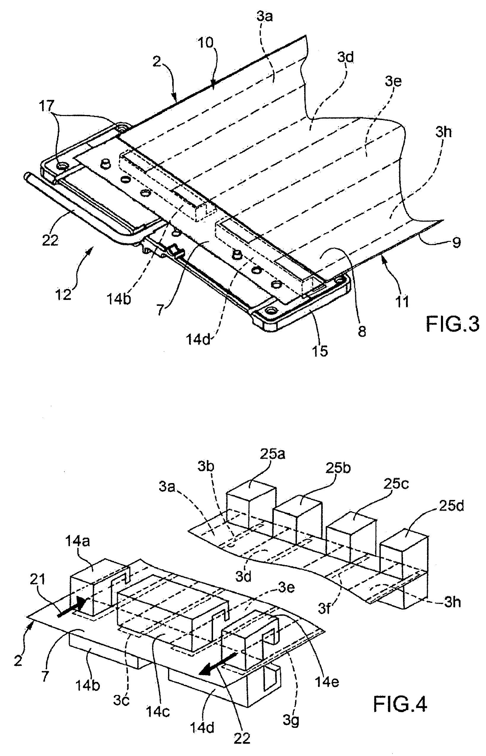
[0031]The device 1 comprises a flexible band, wholly indicated with 2, provided with laminar conductor means 3, which shall be described better hereafter. The laminar conductor means 3a, 3b, 3c, 3d, 3e, 3f, 3g, 3h are directly connected to the electrical mains, thus supplied with normal mains voltage, and therefore they are crossed by current so as to diffuse the heat, by the Joule effect, in the room in which the device is installed, for example a bedroom, a lounge, etc.

[0032]The flexible band 2 also comprises laminar insulating means, wholly indicated with 4 and of the per se known type, associated with the laminar conductor means 3 in the way that will be described h...


PUM


Abstract

Heating device, including a flexible band provided with laminar conductor means crossed by current and suitable for diffusing heat into the environment and laminar insulating means associated with said laminar conductor means, wherein said conductor means includes a plurality of conducting strips, of smaller width than that of said flexible band, electrically connected to one another.

Description

CROSS REFERENCE TO RELATED APPLICATIONS[0001]This application is a Continuation application of U.S. patent application Ser. No. 13 / 811,549 entitled “Heating Device,” which is the National Stage application under 35 U.S.C. 371 of International Application No. PCT / IB2010 / 053349 filed Jul. 22, 2010 and incorporated herein by reference in its entirety.TECHNICAL FIELD OF THE INVENTION[0002]The present invention concerns a heating device.[0003]More specifically, the present invention concerns a heating device consisting of a flexible band to be installed under the surface of a wall or of a floor.STATE OF THE ART[0004]Heating devices consisting of flexible bands are known that comprise laminar conductor means that diffuse heat into the environment through the heating that they undergo when they are crossed by a suitable current, this heating being known as the Joule effect. The aforementioned conductor means, usually in the form of sheets or bands of aluminum of low thickness, are associat...

Claims


Application Information

Patent Timeline
Patent Type & Authority Applications(United States)
IPC IPC(8): H05B3/10
CPCH05B3/10H05B2203/005H05B3/34
Inventor STABILE, ALDO
Owner THERMO ENG
Why Eureka
Try Eureka