Pruning machine

A pruning machine and button technology, applied in the field of pruning machines, can solve the problems of large bending resistance of the flexible steel wire shaft, affecting the transmission function, hindering the normal opening and closing of the pruning machine, etc., achieving simple and direct connection and reduced bending resistance Effect

Inactive Publication Date: 2016-08-24
CHONGQING GUANTAI TECH CO LTD
View PDF0 Cites 0 Cited by
  • Summary
  • Abstract
  • Description
  • Claims
  • Application Information

AI Technical Summary

Problems solved by technology

[0003] In the prior art, the pruning machine that uses the flexible wire shaft to realize the linkage of the main and auxiliary buttons has the following two shortcomings in practical application: 1. The flexible wire shaft is a transmission part that can be bent in any direction to bypass various obstacles , in the pruning machine, although the flexible steel wire shaft can use its own bending characteristics to go around various parts in the pruning machine to realize the linkage of the main and auxiliary buttons, however, due to the large bending resistance of the flexible steel wire shaft (especially in the case of corrosion Afterwards, its bending resistance is greater), and the force arm of the lever that is in contact with or separated from the micro-movement is far away from the force of the secondary button, so that the user must use a large force to not turn on and off the machine, giving The operation brings some inconvenience; 2. The motor in the pruning machine will have a normal heating phenomenon during long-term work. When the temperature is too high, the wire flexible shaft transmission part will And the plastic parts connected with the flexible steel wire shaft are deformed by force and heat, which affects their normal transmission function, which eventually hinders the normal opening and closing of the pruning machine and reduces the reliability of the pruning machine.

Method used


Image

  • Pruning machine
  • Pruning machine

Examples


Embodiment Construction

[0015] The present invention will be further described below in conjunction with accompanying drawing and specific embodiment:

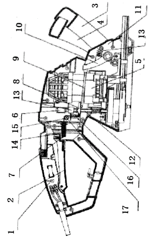
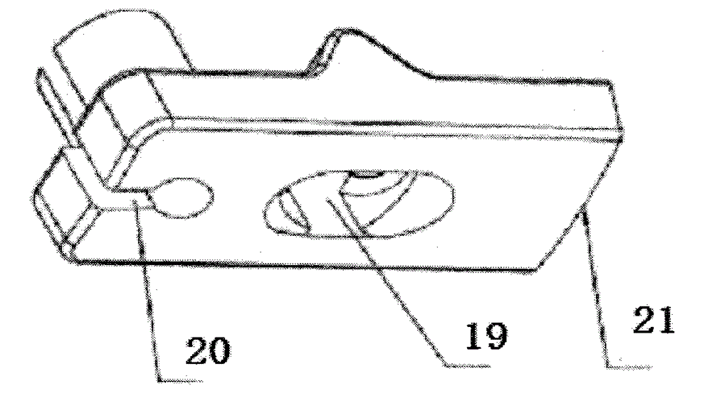
[0016] Such as figure 1 As shown, in this specific embodiment, the left end of the main button 2 is hinged below the main handle 1; Above, since the lower end of the auxiliary button 4 is fixedly connected with the lower end of the pull plate 10, the lower end of the auxiliary button 4 can also be regarded as hinged with the casing 11; the right end of the main button 2 is connected with one end of the flexible steel wire shaft 7, and The other end of the flexible wire shaft 7 is connected to the left end of the seesaw 8; In this specific example, if figure 2 As shown, the seesaw 8 is similar to the lever in the prior art pruning machine, and its function is to generate a force on the micro switch 6, thereby opening or closing the motor assembly 5 electrically connected to the micro switch 6, so A through hole 19 is provided in the middle of the ...


PUM


Abstract

The invention discloses a pruning machine, wherein a steel wire flexible shaft (7), an upright rod (12), a switch top block (13), a main button (2), a lifting plate (8) and a microswitch (6) are arranged at the left of a motor component (5); a draw plate (10) and an auxiliary button (4) are arranged at the right of the motor component (5); two ends of the steel wire flexible shaft (7) are respectively connected with the right end of the main button (2) and the left end of the lifting plate (8); a rigid metal rod (9) is connected between the right end of the lifting plate (8) and the upper end of the draw plate (10); the lower ends of the draw plate (10) and the auxiliary button (3) are hinged with a shell (11) at the same time; the lifting plate (8) is slidably sheathed on the upright rod (12) sheathed by the switch top block (13); and the microswitch (6) is above the switch top block (13). The pruning machine disclosed by the invention has the advantages that a motor can be turned on and off with a relatively small force and thermal deformation of driving components caused by the heating of the motor can be prevented.

Description

technical field [0001] The present invention relates to a pruning machine for pruning or trimming branches, shrubs or hedges and the like. Background technique [0002] For safety considerations, most of the prior art pruning machines need both hands to operate simultaneously to start the machine, that is, the main and auxiliary buttons must be linked to move the micro switch in the casing to start the pruning machine. The patent for invention of the safety control mechanism of the pruning machine authorized by the applicant on June 30, 2004 has disclosed a kind of front and rear handles that are all driven by a flexible wire shaft (also called a flexible wire shaft). The structure of the pruning machine of the joint control machine, which includes a micro switch installed in the main handle to control whether the motor of the pruning machine works, a main button hinged under the main handle, and a button hinged at one end of the auxiliary handle. The auxiliary button and t...

Claims


Application Information

Patent Timeline
Patent Type & Authority Applications(China)
IPC IPC(8): A01G3/08
Inventor 张彩鹏张梦婷
Owner CHONGQING GUANTAI TECH CO LTD
Why Eureka
Try Eureka