Tube or Pipe Clamp

a technology of tube or pipe clamping and nut, which is applied in the direction of pipe-joints, flanged joints, mechanical devices, etc., can solve the problems of limited unthreading of nut, and achieve the effect of reducing the chance of inadvertent clamp opening

Active Publication Date: 2013-09-26
SANI TECH WEST INC
View PDF3 Cites 31 Cited by
  • Summary
  • Abstract
  • Description
  • Claims
  • Application Information

AI Technical Summary

Benefits of technology

[0006]A more particular object of the present invention is to provide a tube or pipe clamp wherein the chances of inadvertent clamp opening is reduced.

Problems solved by technology

Where the shaft is a bolt and the locking element is a nut (e.g., wing nut) loosening may result in part from a limited unthreading of the nut relative to the bolt.

Method used


Image

  • Tube or Pipe Clamp
  • Tube or Pipe Clamp
  • Tube or Pipe Clamp

Examples


Embodiment Construction

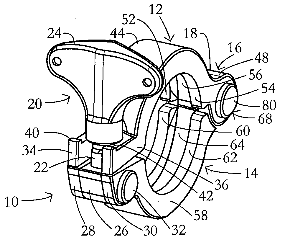
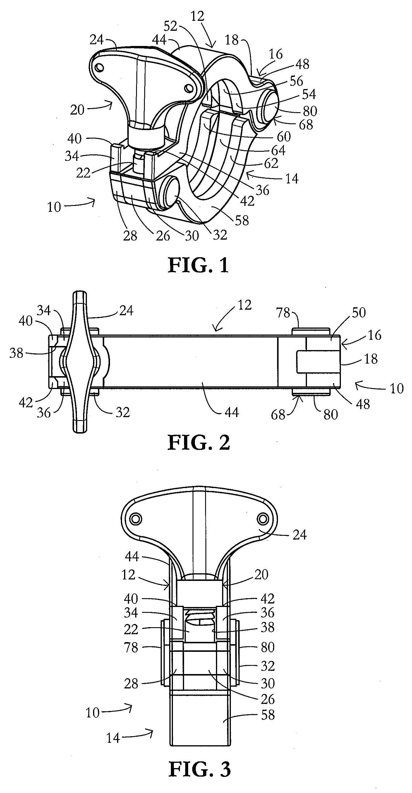
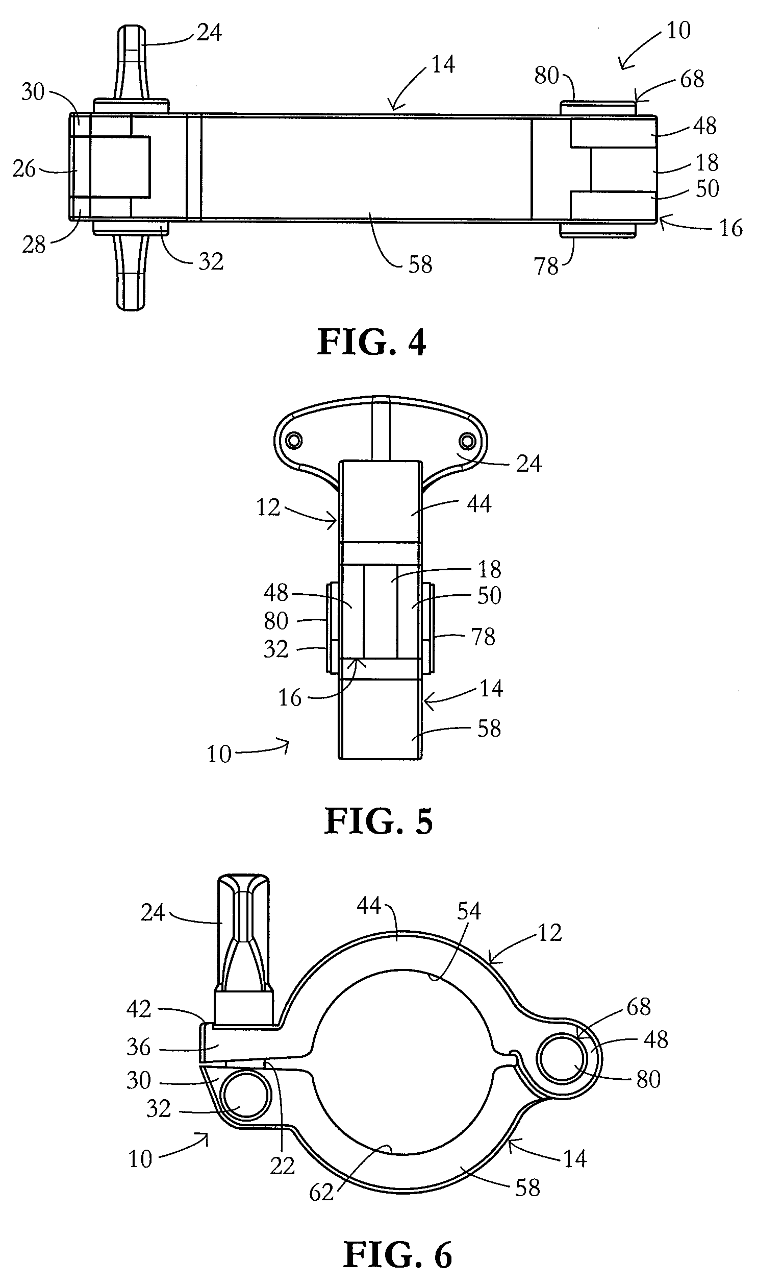
[0029]A tube or pipe clamp 10 includes an upper clamp half or member 12 and a lower clamp half or member 14. Clamp members 12 and 14 are pivotably connected to one another at respective hinge-forming ends 16, 18 thereof. Tube or pipe clamp 10 also includes a locking device 20, which comprises a shaft 22 specifically in the form of a bolt and a locking element 24 specifically in the form of a wing nut.

[0030]Shaft or bolt 22 is pivotably attached to a lower one 14 of the clamp members 12, 14. More specifically, bolt 22 is anchored to or embedded in a base plate 26 that is slidably ensconced in a space (not separately designated) between two mutually parallel flanges 28 and 30 on a side of lower clamp member 14 opposite hinge-forming end 18. Base plate 26 and accordingly bolt 22 are swingably mounted to flanges 28 and 30 via a pivot pin 32 (only head portions are visible).

[0031]Upper clamp member 12 has a pair of prongs 34 and 36 disposed in coplanar alignment with respective flanges 2...


PUM


Abstract

A tube or pipe clamp has two clamp members that are pivotably connected to one another at respective hinge-forming ends thereof. The tube or pipe clamp has a locking device that includes a shaft and a locking element operatively attached to the shaft, the shaft being pivotably attached to one of the clamp members. The other clamp member has a pair of prongs defining a slot for receiving the shaft of the locking device, the locking element being engageable with the prongs to lock the clamp members to one another at ends thereof opposite the hinge-forming ends. The prongs each have at least one projection on a side facing away from the one clamp member. Each of the projections is disposed proximate the free end of the respective prong.

Description

BACKGROUND OF THE INVENTION[0001]This invention relates to tube or pipe clamps.[0002]Tube clamps are used extensively in industry to fixedly attached two adjacent tubes end to end in a flanged ferrule tube connection. The ferrules have angled (conical) surfaces. A tube clamp captures the ferrules and contacts them on the conical faces. By clamping the clamp diametrically, the contact on the angled surfaces causes a linear force component to squeeze the ferrules together in a direction that squeezes a gasket disposed between them.[0003]Industry has various problems with this type of clamp, including loosening of the wing nuts, causing them to sometimes swing open.[0004]Participants in the industry and industry standards-creating bodies have attempted to solve this problem by introduction of standard component configurations and new products. Products include metal-to-metal ferrules with fixed gasket space, various durometer gaskets, hard gaskets, gasket appendages to achieve fixed fe...

Claims


Application Information

Patent Timeline
Patent Type & Authority Applications(United States)
IPC IPC(8): F16L23/04
CPCF16L23/04F16L23/10
Inventor MCKIERNAN, KEVIN
Owner SANI TECH WEST INC
Why Eureka
Try Eureka