Suspension Mechanism for an Optical Image Anti-Shake Device

US20130258475A1Active Publication Date: 2013-10-03TDK TAIWAN

Image

  • Suspension Mechanism for an Optical Image Anti-Shake Device
  • Suspension Mechanism for an Optical Image Anti-Shake Device
  • Suspension Mechanism for an Optical Image Anti-Shake Device

Examples


first embodiment

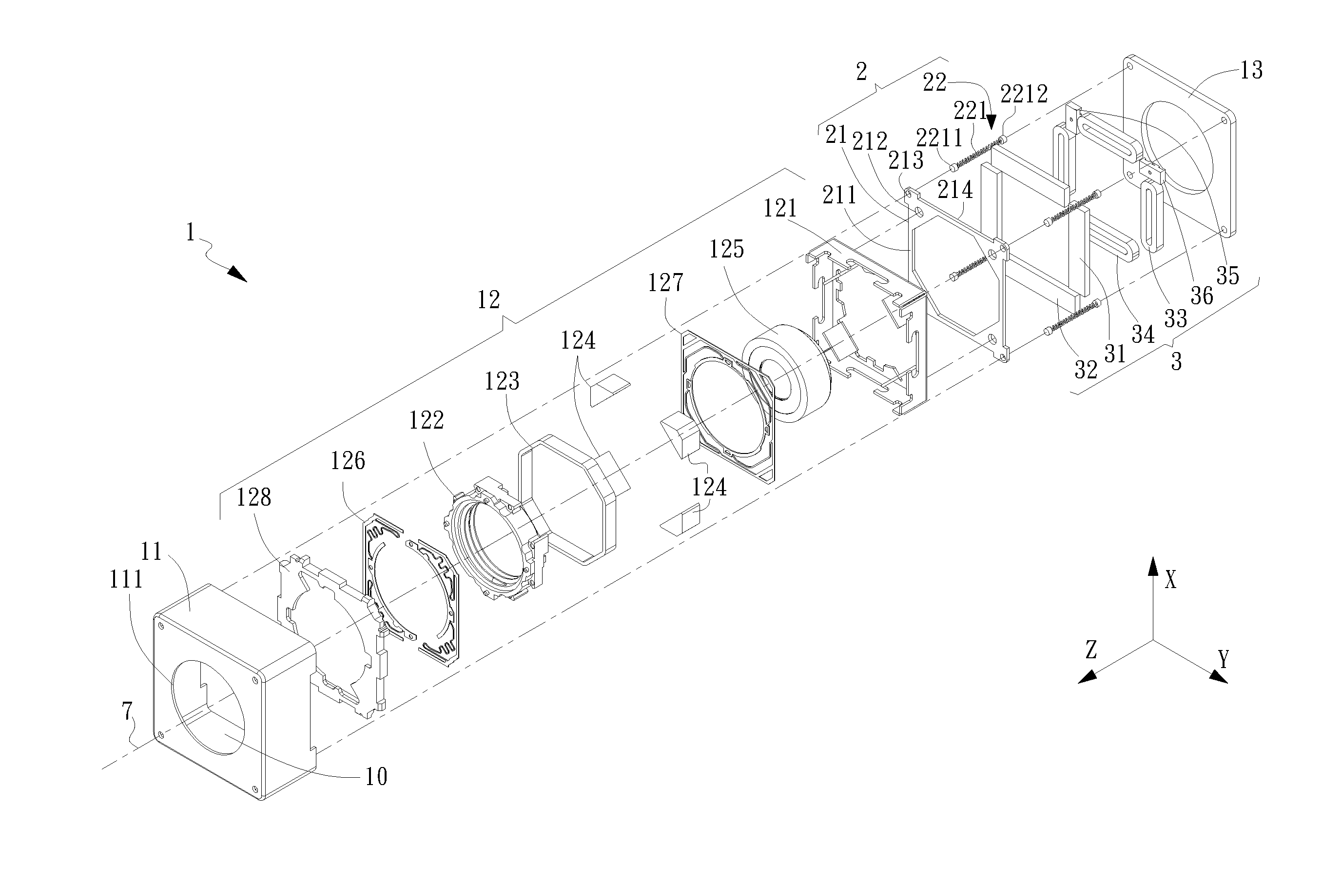
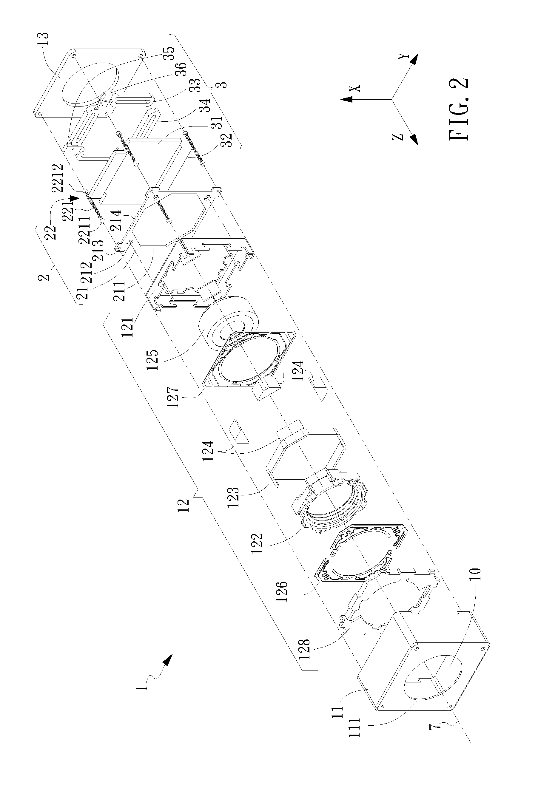
[0030]Refer now to FIG. 2, FIG. 3, FIG. 4, FIG. 5 and FIG. 6, in which FIG. 2 is a schematic exploded view of an optical image anti-shake device having the suspension mechanism in accordance with the present invention, FIG. 3 is a top view of FIG. 2, FIG. 4 is a cross-sectional view of FIG. 3 along line A-A, FIG. 5 is a cross-sectional view of FIG. 3 along line B-B, and FIG. 6 is an enlarged exploded view of the suspension mechanism of FIG. 2.

[0031]In the present invention, the optical image anti-shake device 1 to carry the first embodiment of the suspension mechanism 2 is defined with an orthogonal coordinate system having an X-axis, a Y-axis and a Z-axis. The optical image anti-shake device 1 includes a casing 11, a movable member 12 and a base 13. The suspension mechanism 2 furnished inside the optical image anti-shake device 1 includes a movable-member support and a suspension module 22. A first surface 211 of the movable-member support 21 is adhered to the movable member 12 ins...

second embodiment

[0043]In the second embodiment, the movable-member support 21a and the frame 223a are both thin-plate structures having individual upper surfaces parallel to the X-Y plane. Preferably, the movable-member support 21a and the frame 223a are located at the same X-Y plane and have almost the same thickness. In particular, the movable-member support 21a, the elastic elements 224a and the frame 223a are produced as a single piece from stamping the same thin metal plate. The frame 223a has a central hollow portion 2232a for receiving the movable-member support 21a. A surrounding gap with preset spacing t1 exists between the inner movable-member support 21a and the outer frame 223a. The elastic elements 224a are mounted in an equilibrium manner in the surrounding gap t1 to space the frame 223a and the movable-member support 21a. Each of the elastic elements 224a has a first end 2241a and an opposing second end 2242a to connect with an outer rim 215a of the movable-member support 21a and an ...


PUM


Abstract

An optical image anti-shake device, defined with an X-axis, a Y-axis and a Z-axis, includes a casing, a movable member and a base. A suspension mechanism furnished inside the optical image anti-shake device includes a movable-member support and a suspension module. A first surface of the movable-member support is connected to the movable member. The suspension module suspends the movable-member support together with the movable member inside an inner compartment formed between the casing and the base.

Description

BACKGROUND OF INVENTION[0001]1. Field of the Invention[0002]The invention relates to a suspension mechanism for an optical image anti-shake device, by which the anti-shake strength of a lens module in the optical image anti-shake device can be increased to a degree that possible permanent deformation thereof can be avoided while in meeting an accidental fall.[0003]2. Description of the Prior Art[0004]Digital photography technology has been widely applied to most of the portable electronic devices such as the cellular phones. Various miniaturized techniques in the lens module are involved to make all these applications possible; in particular, the voice coil motor (VCM) technique. The VCM introduces a combination of coiled magnets and spring plates to drive a lens to move back and forth along a photo axis for image-capturing, so as to perform auto-zooming and / or auto-focusing of the lens module. Further, in this trend of demanding for devices capable of high-level photographing funct...

Claims


Application Information

Patent Timeline
03 Oct 2013
Publication
US20130258475A1
IPC
G02B27/64
CPC
G02B7/102; G02B27/646; G03B3/10; G03B2205/0053; G03B2205/0015; G03B2205/0046; G03B5/00; G02B7/09
Inventors
LEE, JIN YU