Resistive braking via screed heating

a technology of resistive braking and screed heating, which is applied in the direction of roads, roads, construction, etc., can solve the problems of reduced performance, reduced performance, and difficulty in meeting the minimum stopping time/maximum stopping distance requirements of tractor or other pulling machines coupled to multiple filled screeds

Active Publication Date: 2013-10-03
CATERPILLAR PAVING PROD INC
View PDF0 Cites 6 Cited by
  • Summary
  • Abstract
  • Description
  • Claims
  • Application Information

AI Technical Summary

Problems solved by technology

In particular, a tractor or other pulling machine coupled to multiple filled screeds may have difficulty meeting minimum stopping time / maximum stopping distance requirements due to the additional mass of the screeds and their contents.
However, the heat cycling of the hydraulic fluid may negatively impact fluid life and may also at least temporarily degrade fluid performance, leading to reduced performance as well as a requirement for more frequent fluid replacement.
Moreover, the hydraulic fluid may have a maximum heat capacity that is less than that required to effectively stop the machine under more challenging circumstances.
In short, mechanisms for extracting and dissipating excess paving machine speed have not, to date, been entirely acceptable.

Method used


Image

  • Resistive braking via screed heating
  • Resistive braking via screed heating
  • Resistive braking via screed heating

Examples


Embodiment Construction

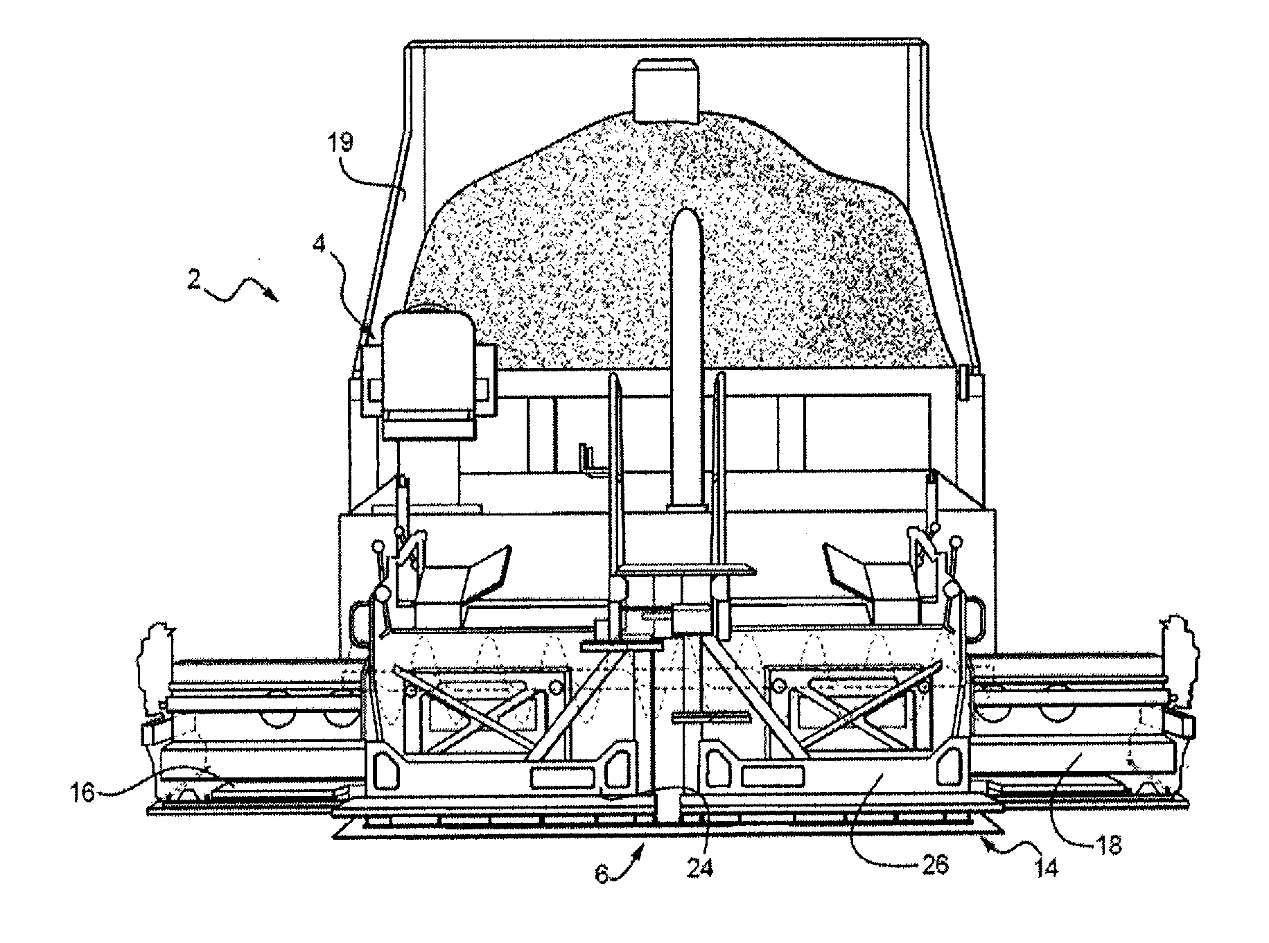
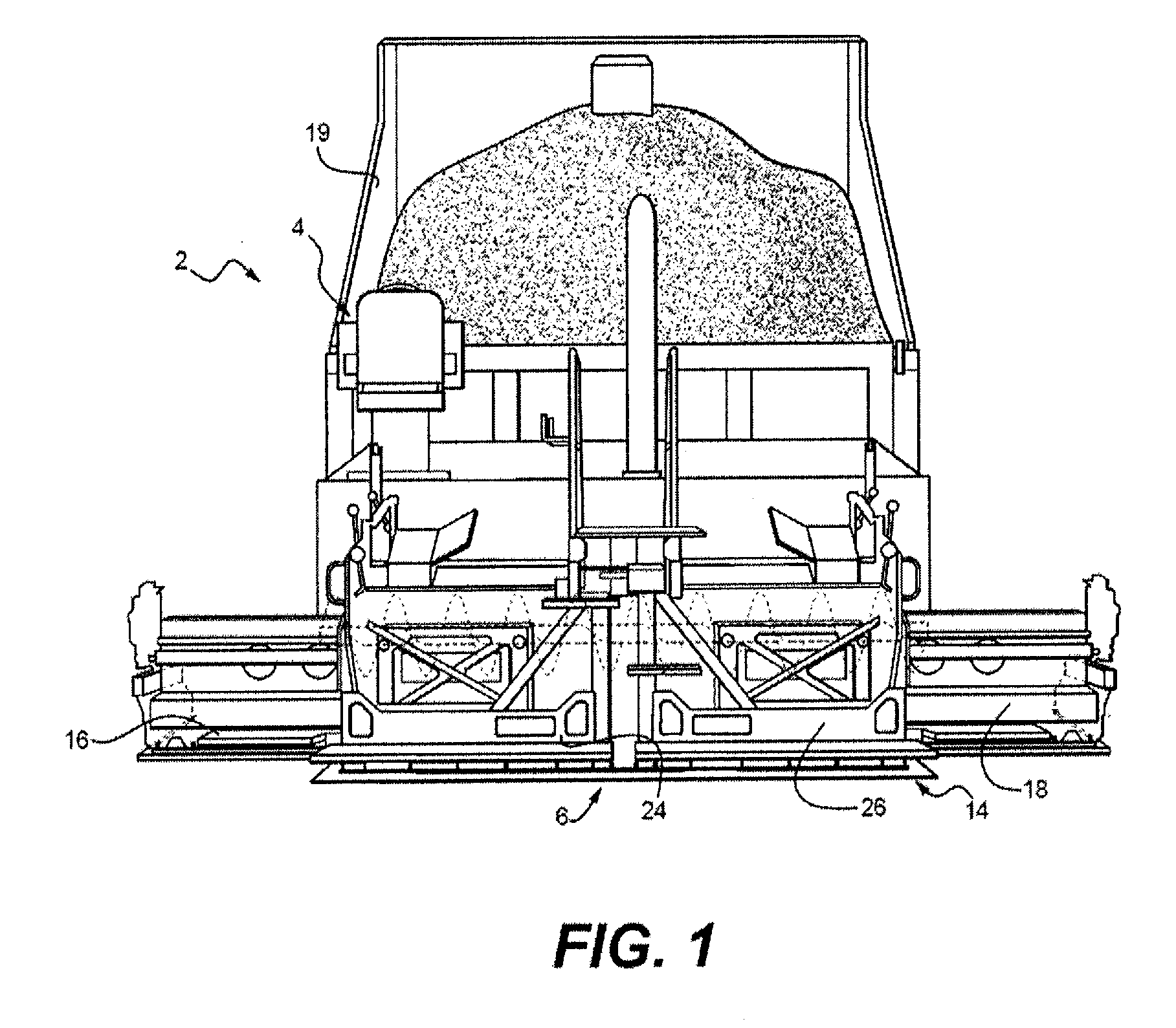
[0016]The present disclosure provides a system and method for the braking of paving machines via hydroelectric screed plate heating. Referring now to FIG. 1, an exemplary paving system 2 is schematically shown, in accordance with one or more embodiments of the present disclosure. It will be understood that only those components that are helpful for a proper understanding of the present disclosure are shown and / or described herein. Nevertheless, several other components that are commonly employed in combination or conjunction with such paving machines are contemplated and considered within the scope of the present disclosure.

[0017]In the illustrated embodiment, the paving system 2 includes a tractor 4 towing a screed assembly 6. The tractor 4 may include an engine, a transmission and wheels, tracks or other locomotive devices for moving the tractor 4 and coupled screed assembly 6. In an embodiment, the engine drives a hydraulic pump to generate pressurized hydraulic fluid used to pro...


PUM


Abstract

A method and various apparatus are provided for assisting braking in a paving machine having hydraulically driven ground engaging elements driven by a hydraulic motor, and one or more screed electrical heating elements powered by a generator. In the event that the application of the machine deceleration system occurs at a machine speed exceeding a predetermined threshold value, the hydraulic motor of the drive train is configured to drive the hydraulic pump of the hydraulic system. The hydraulic pump is linked to the system generator to generate electrical power to drive the one or more screed electrical heating elements at a current greater than the current previously being provided to the one or more screed electrical heating elements.

Description

TECHNICAL FIELD OF THE DISCLOSURE[0001]The present disclosure relates to paving machines and, more particularly, relates to braking of paving machines via screed plate heating.BACKGROUND OF THE DISCLOSURE[0002]Asphalt roadways are generally constructed by laying heated paving material, such as bituminous aggregate mixtures or asphalt onto a roadbed. After the heated asphalt is laid, it is typically spread, leveled and compacted such that upon cooling, a road with a uniform, smooth surface that is passable by vehicles is achieved. In order to spread the heated asphalt, a paving machine, known as a screed, may be used. Such screeds can be pulled by a tractor, truck or the like or can be self-propelled. The truck or the tractor supplies the asphalt and the screed then heats, vibrates and manipulates the asphalt into a smooth uniform surface. A screed generally employs a screed assembly having one or more separable screed units.[0003]The screed may represent a significant portion of ove...

Claims


Application Information

Patent Timeline
Patent Type & Authority Applications(United States)
IPC IPC(8): E01C23/14E01C19/12E01C19/18
CPCE01C2301/10E01C19/48
Inventor THIESSE, RYAN T.FRELICH, TOBY A.
Owner CATERPILLAR PAVING PROD INC
Why Eureka
Try Eureka