3D stereoscopic camera module

a stereoscopic camera and camera module technology, applied in the field of 3d stereoscopic camera modules, can solve the problems of inadequate 3d stereoscopic and inability to shoot relatively short distances 3d stereoscopic images, and achieve excellent short-distance 3d stereoscopic shooting and ease of convergence angle control

Active Publication Date: 2013-10-10
LG INNOTEK CO LTD
View PDF12 Cites 25 Cited by
  • Summary
  • Abstract
  • Description
  • Claims
  • Application Information

AI Technical Summary

Benefits of technology

[0016]A 3D stereoscopic camera module according to the present invention has an advantageous effect in that the 3D stereoscopic camera is so configured as to be vertically and horizontally driven and tilted to ease a convergence angle control and to enable an excellent short-distanced 3D stereoscopic shooting.

Problems solved by technology

The conventional 3D stereoscopic camera is however disadvantageous in that it may be adequate to shoot mid / far distanced 3D stereoscopic images but inadequate to shoot relatively short distanced 3D stereoscopic images because an actuator moves horizontally only.

Method used


Image

  • 3D stereoscopic camera module
  • 3D stereoscopic camera module
  • 3D stereoscopic camera module

Examples


Embodiment Construction

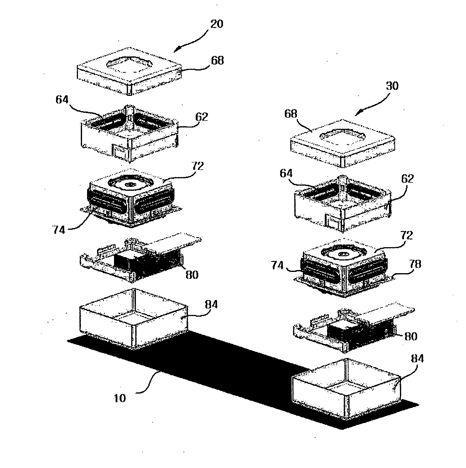
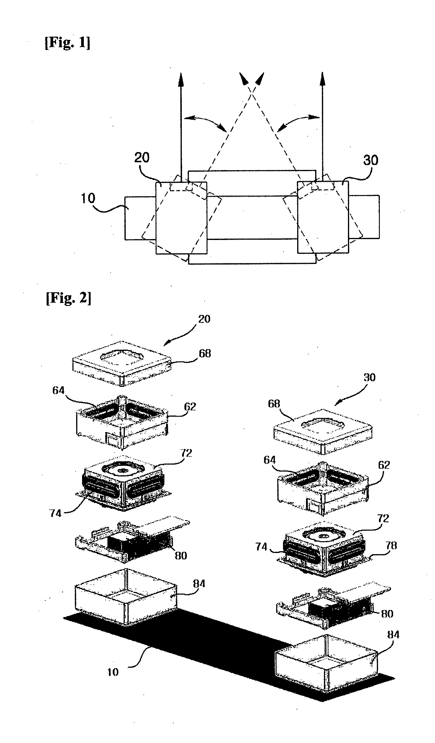
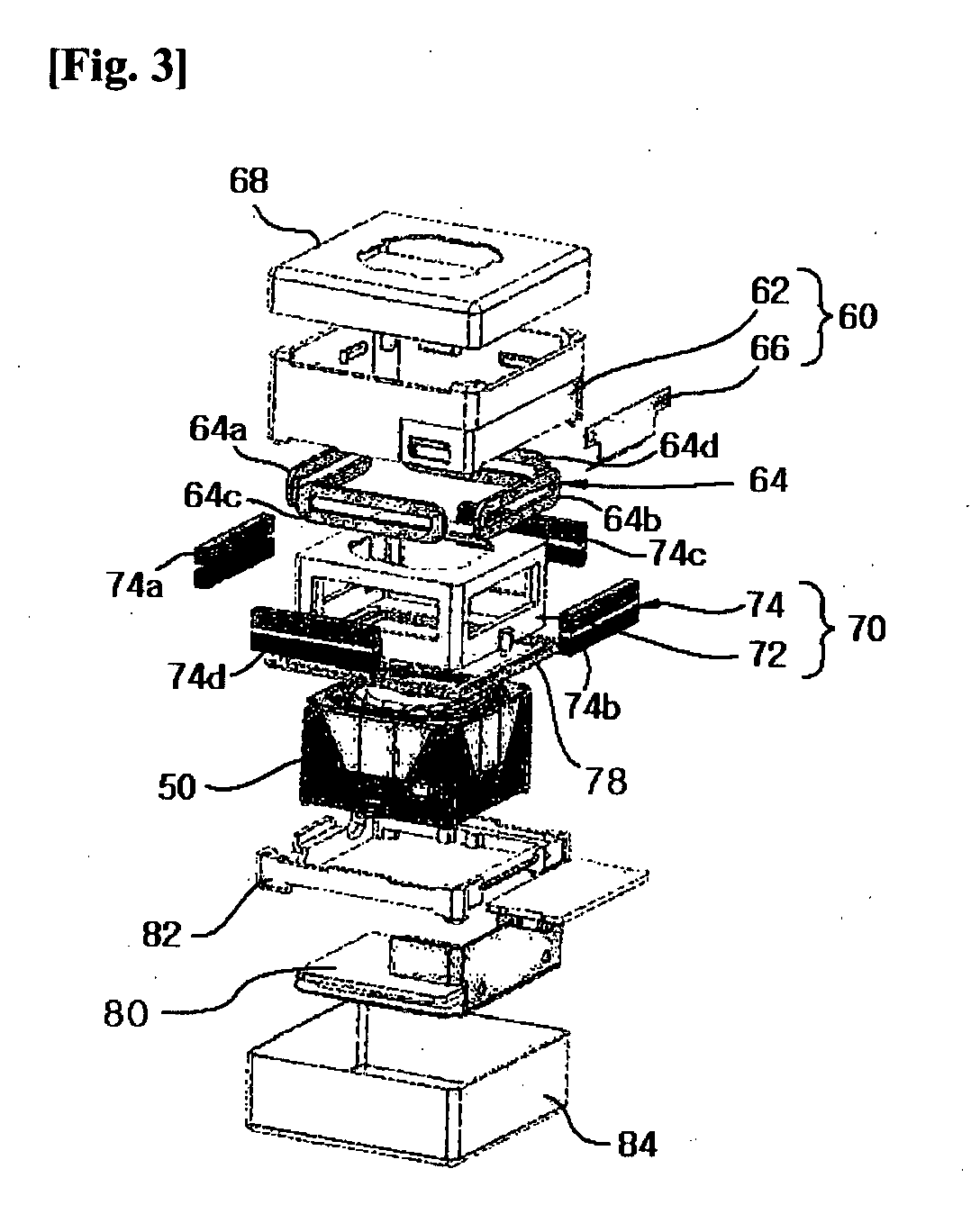
[0021]The disclosed embodiments and advantages thereof are best understood by referring to FIGS. 1-4 of the drawings, like numerals being used for like and corresponding parts of the various drawings. Other features and advantages of the disclosed embodiments will be or will become apparent to one of ordinary skill in the art upon examination of the following figures and detailed description. It is intended that all such additional features and advantages be included within the scope of the disclosed embodiments, and protected by the accompanying drawings. Further, the illustrated figures are only exemplary and not intended to assert or imply any limitation with regard to the environment, architecture, or process in which different embodiments may be implemented. Accordingly, the described aspect is intended to embrace all such alterations, modifications, and variations that fall within the scope and novel idea of the present invention.

[0022]Meanwhile, the terminology used herein is...


PUM


Abstract

The present invention relates to a 3D stereoscopic camera module, the module including an upper case, and left and right cameras arranged on the upper case, each formed at a pre-determined space apart, wherein the left and right cameras include at least three or more coils arranged at an inner surface of the upper case, a housing arranged inside the upper case and mounted therein with a lens, at least three or more magnets mounted at the housing to face the coils, and an image sensor converting an optical signal of an image captured by the lens to an electrical signal, whereby a convergence angle can be easily controlled and an excellent short-distanced 3D stereoscopic shooting can be realized.

Description

TECHNICAL FIELD[0001]The present invention relates to a 3D stereoscopic camera module enabling to realize a 3D image.BACKGROUND ART[0002]Generally, two sheets or more of 2D images having mutually effective time difference are needed to realize 3D stereoscopic images. A camera employed for obtaining two sheets or more of 2D images is called a 3D stereoscopic camera. There exist various techniques and systems for producing 3D (three-dimensional) images. One type of approach is a dual lens 3D image photographing method and another type of approach is a multi-view 3D image photographing method. However, the dual lens camera is largely used.[0003]A conventional 3D stereoscopic camera is configured in such a manner that two fixed image sensors are arranged thereon with two actuators which are horizontally moved to change a position where light from a lens is captured on the image sensor, whereby a convergence angle control can be performed.[0004]The conventional 3D stereoscopic camera is ...

Claims


Application Information

Patent Timeline
Patent Type & Authority Applications(United States)
IPC IPC(8): H04N5/225
CPCH04N5/2253H04N13/0239H04N13/239H04N23/54
Inventor LIM, HAEKEUN
Owner LG INNOTEK CO LTD
Why Eureka
Try Eureka