Crushing body and method of making the same

a technology of crushing body and body, applied in the field of crushing body, can solve the problems of wearable surface, wearable surface often experiences wear, parts of wearable surface may erode or become broken, and achieve the effect of improving the stability and ultimately the life of the inser

Inactive Publication Date: 2013-11-14
F L SMIDTH & CO AS
View PDF0 Cites 28 Cited by
  • Summary
  • Abstract
  • Description
  • Claims
  • Application Information

AI Technical Summary

Benefits of technology

[0009]A method of making a crushing body for a crushing device, the crushing body, and the crushing device are provided herein. Embodiments of the method may provide for making a crushing body that can be used in crushing devices that may use a combination of mechanical and chemical attachment to be utilized for attaching inserts to the crushing body to improve the stability and ultimately the life of the inserts. Inserts may be securely attached to a crushing body to help prevent insert damage to occur when a crushing body is used to comminute material such as ore, rock, stone, agglomerated material, material used to make cement, materials to make minerals, or other materials.
[0011]Preferably, embodiments of the method may form a crushing body that is able to provide multiple fastening methods to the inserts that won't deplete or wear, which can help mitigate or avoid insert damage that could occur when the crushing body is used to crush material. For instance, the inserts may be interlocked between the wear body and mounting body portions of the crushing body and also glued to the wear body, the mounting body, or both when positioned in the channels of the wear body.
[0012]Embodiments of the method may permit inserts to be pushed, pulled, screwed, or pressed through or into the channels of the wear body through a side or surface of the wear body that is on the crushing surface of the wear body or opposite the crushing surface of the wear body. Mechanical attachment provided by fasteners or a fastening mechanism may also be provided adjacent to the side of the wear body that is opposite the crushing surface of the wear body. The mechanical attachment of the inserts may help retain the inserts even if a portion of the insert is fracture or broken so that the whole insert does not fall out from the wear body. Moreover, the use of glue or other bonding agent may help keep the inserts affixed within the wear body and help better distribute loading the inserts experience to the wear body, which can help increase the life of the inserts. It should be appreciated that mechanically loading the inserts while also incorporating the chemical bonding via glue or another adhesive may assist in the load distribution and stabilization of the inserts within the crushing body.
[0015]In some embodiments, the wear body may be configured to have a plurality of material dams. The material dams may be positioned on the crushing surface of the wear body to help retain material and prevent material from flowing away from crushing forces being applied to the material. For instance, if the crushing body is a roller, the material dams may prevent material from flowing in an axial direction away from crushing forces being applied by the roller rotating along an axis. It should be appreciated that the axis may define the axial directions. The material dams may be affixed to the wear body such that the material dams are replaceably attached by removing one or more fasteners to replace a worn or damaged material dam with a new material dam. The fasteners may be preferably removed without having to disconnect the mounting body from the wear body or disconnect the crushing body from an axle or other component of a crushing device when the crushing device is positioned in a crushing circuit or other material processing facility.
[0024]The wear body may be formed in any of a number of ways. For instance, the wear body may be one integrally formed structure, such as a molded structure. As another example, the wear body may be formed with the mounting body such that both the mounting body and the wear body are portions of an integrally formed structure or an integrally cast structure. As yet another example, the wear body may be formed by connecting at least one outer portion to at least one inner portion. The inner and outer portions may define the crushing surface of the wear body. The one or more inner portions may be composed of a material that is harder or softer than the material of the one or more outer portions so that the crushing surface experiences wear differently at different locations. For instance, the inner and outer portions may be composed of metal or a composite material that have different hardnesses. Preferably, the outer portions include at least one side that has a profile configured to mate or interconnect with the profile of a side of an inner portion. The mating profiles may help strengthen the connection between the inner and outer portions.

Problems solved by technology

Crushing bodies often include a wearable surface.
The wearable surface often experiences wear as material is crushed by the crushing body.
As the crushing body experiences wear, portions of the wearable surface may erode or become broken during use and subsequently requires replacement or repair.
During use, the tiles can break free from the base material when crushing material, which may expose the base material to the grinding process and thereby damage the base material.
However, because the base material is often exposed to grinding forces, the reattachment or replacement of any missing tile may result in a less secure attachment than what was initially provided, which may make the tile more likely to again break free during use.
Rollers with such a wear surface often experience insert cracking, breaking or fall out because the glue or adhesive fails to provide a sufficient bond with a roll body to withstand the extreme pressures associated with grinding and crushing material.
As a result, the inserts may fall out or become damaged.
Replacement of such inserts may be very time consuming if binding rings are again used to reattach the new inserts.

Method used


Image

  • Crushing body and method of making the same
  • Crushing body and method of making the same
  • Crushing body and method of making the same

Examples


Embodiment Construction

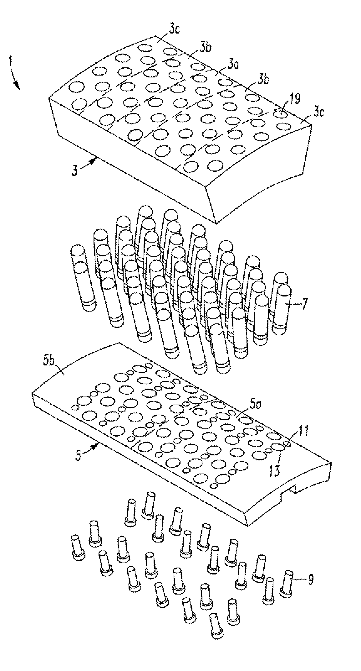
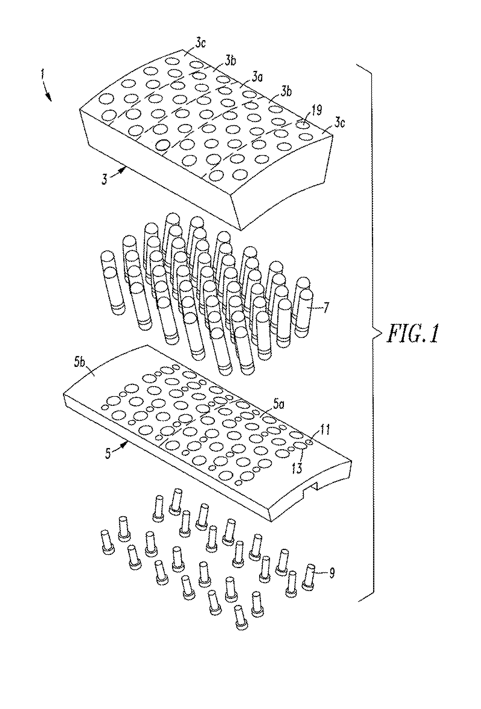
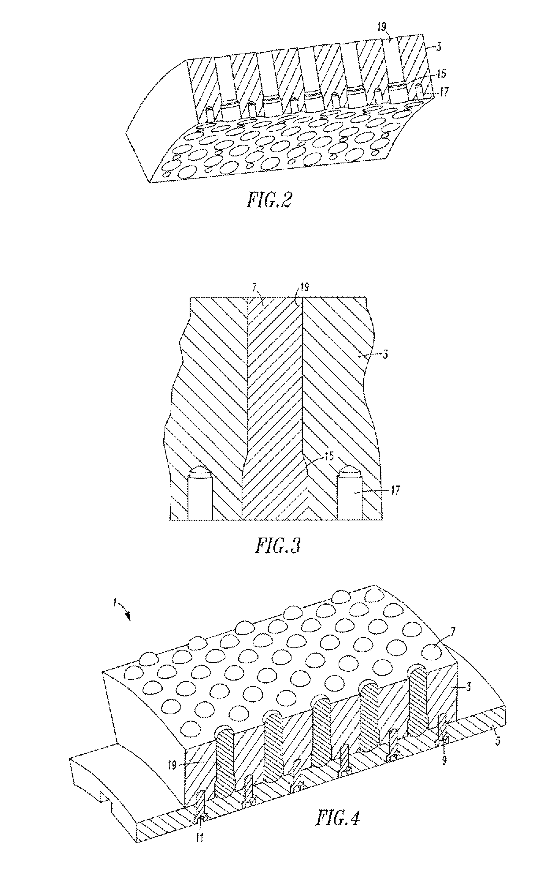
[0053]Referring to FIG. 1, a crushing body 1 may include a wear body 3 that is attached to a mounting body 5. Inserts 7 may be positioned between the wear body 3 and the mounting body 5. A portion of each insert 7 may be positioned in a respective channel 19 of a plurality of channels 19 formed in the wear body 3. Each insert 7 may have a base portion 8 that fits within a recess 13 or aperture formed in the mounting body 5. Alternatively, the base portion 8 of each insert 7 may be supported by a boss or raised portion of the mounting body 5 (not shown).

[0054]Fasteners 9 may extend through holes 11 or other apertures in the mounting body 5 and into apertures or grooves 17 formed in the wear body 3, such as threaded openings formed in inserts positioned in the wear body 3, to mechanically attach the mounting body 5 to the wear body 3. Of course, the mounting body 5 may also be attached via an adhesive, welding or bonding agent in addition to the mechanical connection provided by the f...


PUM

PropertyMeasurementUnit
widthaaaaaaaaaa
diameteraaaaaaaaaa
grinding forcesaaaaaaaaaa

Abstract

A crushing body includes a wear body, inserts positioned in channels of the wear body, a mounting body positioned adjacent to the inserts and fasteners inserted into the mounting body to connect the mounting body to the inserts, the wear body, or both the inserts and the wear body. Preferably, the inserts are positioned so that a portion of each of the inserts is within the wear body and a base portion is adjacent to or engages the mounting body. Crushing devices such as mills, and crushers may utilize embodiments of the crushing body.

Description

FIELD OF THE INVENTION[0001]The present invention relates to crushing bodies for the comminution of material such as ore, rock, agglomerated material, minerals, stone, material used in the making of cement, minerals and other types of material. Examples of crushing bodies include rollers of roller mills that are configured to grind material or crushing surfaces of crushing devices, such as crushers, grinders, presses, roller presses, jaw crushers, gyratory crushers, vertical grinding mills, other mills or other devices configured to crush material or comminute material. Preferably, the crushing body is configured to have a wearable surface that defines an autogenous layer or semi-autogenous layer.BACKGROUND OF THE INVENTION[0002]Crushing devices used to comminute material often include a crushing body or multiple crushing bodies that are configured to impact material to crush or grind the material. Often the crushing bodies are configured to grind the material between a surface of t...

Claims


Application Information

Patent Timeline
Patent Type & Authority Applications(United States)
IPC IPC(8): B02C23/00
CPCB02C23/00B02C1/10B02C2/005B02C4/305B02C2210/02Y10T29/49947Y10T29/49968Y10T29/49966
Inventor SHARMAN, DAVID
Owner F L SMIDTH & CO AS
Why Eureka
Try Eureka